Misc. rf board changes – Elecraft K2ATOBKIT User Manual
Page 6
6
3. Misc. RF Board Changes
This step describes all RF board changes not covered
elsewhere. Parts can be found in K2ATOBKT.
Turn the K2 off. Touch an unpainted, grounded
metal surface. Remove the top cover.
Remove all options plugged into the RF board.
Remove the two screws holding the Control board
to the Front Panel board. Unplug the KAF2 if present.
Remove the Front Panel assembly (there is no
need to separate the panel from the PC board).
Remove the bottom cover.
Remove the rear panel/heatsink. Save all of the
PA hardware, including the thermal pads.
Revision XC and older Rev. C K2s Only
The following steps apply to Rev. XC and some Rev.
A K2s (prior to s/n 2000). Check the components to
see if you already have the correct values installed.
Change C68 (VCO area) from 4.7 or 5 pF to 10
pF. (Eliminates possible VCO problem on 160 meters.)
Change R1 and R2 (near the key jack) from 470
ohms (or 1k) to 220 ohms. (Lowers the voltage seen by
the K2 when a paddle is closed. With 1 k, noise
immunity may be inadequate. The microcontroller's
internal pull-up resistors can pull these lines up too
close to the "0" logic threshold.)
Change R50 from 1/4 watt to 1/2 watt (1.5 ohms,
brown-green-gold). (1/4 watt in the driver emitter was
too low to ensure adequate heat dissipation.)
Note: Other minor (preventative) design changes were made
from revision XC to revision A. Except in rare cases, they
will not significantly affect performance, and we
recommend that they not be changed. These include: L31
from 12 to 10 µH (PLL reference), C153 from 39 to 68 pF
(TX mixer coupling), C162 from .01 to .047 (post-mixer
amp), D9 from 1N34A to 1N5711 and R68 from 237 to 226
(RF detector).
Revision A and XC K2
Change R64 (center of the board, near U1) from
470 to 100 ohms. (Improves auxBus noise immunity.)
Change RFC11 from an RF choke to an FT37-43
toroid with 20 turns #26 enamel. Mount RFC11 on the
bottom of the board with short leads. (Reduces
unwanted S-meter activation, esp. on 17 meters.)
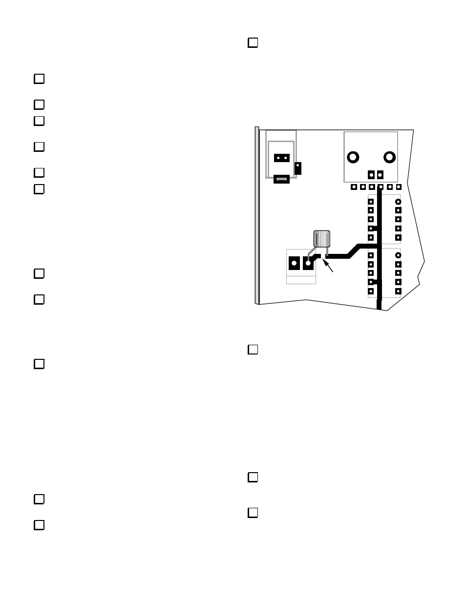
Add C
RF
(.047, "473") on the bottom of the RF
board as shown in Figure 4. One trace cut is required.
(This capacitor is important if you have a KBT2
internal battery or KPA100 module. It prevents
damage to the K2's low-pass filter relays in the event
that the AUX RF and AUX DC cables are reversed. On
the Rev. B RF board, the capacitor is C224.)
K10
J4
K9
P6
J3
Crf
Cut
Figure 4
Change D10, at the right edge of the RF board,
from an SB530 to a 95SQ015. (The latter is an ultra-
low-drop diode, having a drop of only about 0.1 to 0.2
volts. This reduces wasted power in the diode on
transmit, nearly eliminates the discrepancy between
external voltmeters and the K2's internal voltage
display, and allows the use of a slightly lower voltage
supply for recharging the KBT2 internal battery.)
Re-installing the Heat Sink
Note: Skip these two steps for now if you plan to make
the bandpass filter changes on the next page.
Inspect the thermal pads for Q7 and Q8. Brush
away any aluminum fragments which might have
become stuck to the pads.
Re-install the rear panel/heat sink and PA
hardware as described in the K2 owner's manual
(Assembly, Part III).