Pll frequency stability at 7182 khz – Elecraft K2ATOBKIT User Manual
Page 5
5
2. PLL Frequency Stability at 7182 kHz
Whenever the VFO is tuned to the 5 kHz band segment
centered at about 7182 kHz, the PLL reference
oscillator and VCO will be at exactly the same
frequency. At this point, on a small percentage of K2s,
coupling between the two oscillators can result in a
"wavering" quality on both transmit and receive. If
your K2 exhibits this symptom, it must be corrected. It
compromises signal quality, and may prevent VFO
linearization (CAL PLL) from working correctly.
Frequency Stability Test
You'll first need to identify the segment of 40
meters over which the two oscillators are at the same
frequency. Switch to 40 meters, LSB or CW mode, and
tune to about 7182 kHz. Then activate C A L F C T R
using the menu. Alternately insert the internal counter
probe into TP1 (VCO) and TP3 (PLL reference
oscillator), and make sure they indicate the same
frequency (in the 12 MHz range). They'll be equal over
some 5 kHz segment, typically 7179-7184, but
possibly lower or higher
5
. (Note that you can tune the
VFO while in C A L F C T R .) Don't change modes or
filters, as this will move the target range.
Range: 7____- 7____ kHz (mode: ___, filter: ___ )
Listen to a few signals in this range to see if they
exhibit the "wavering" sound. Compare them to signals
outside the range. You can use another ham transmitter
as a signal generator. (Don't change modes or filters.)
Modifications to Cure Instability
The following modifications can be used to cure
the instability, if required. Try them in order, and stop
when the symptom disappears. All necessary parts are
included in mod kit K2ATOBKT.
Make sure C70 and C71 (VCO area) have the shortest
possible leads.
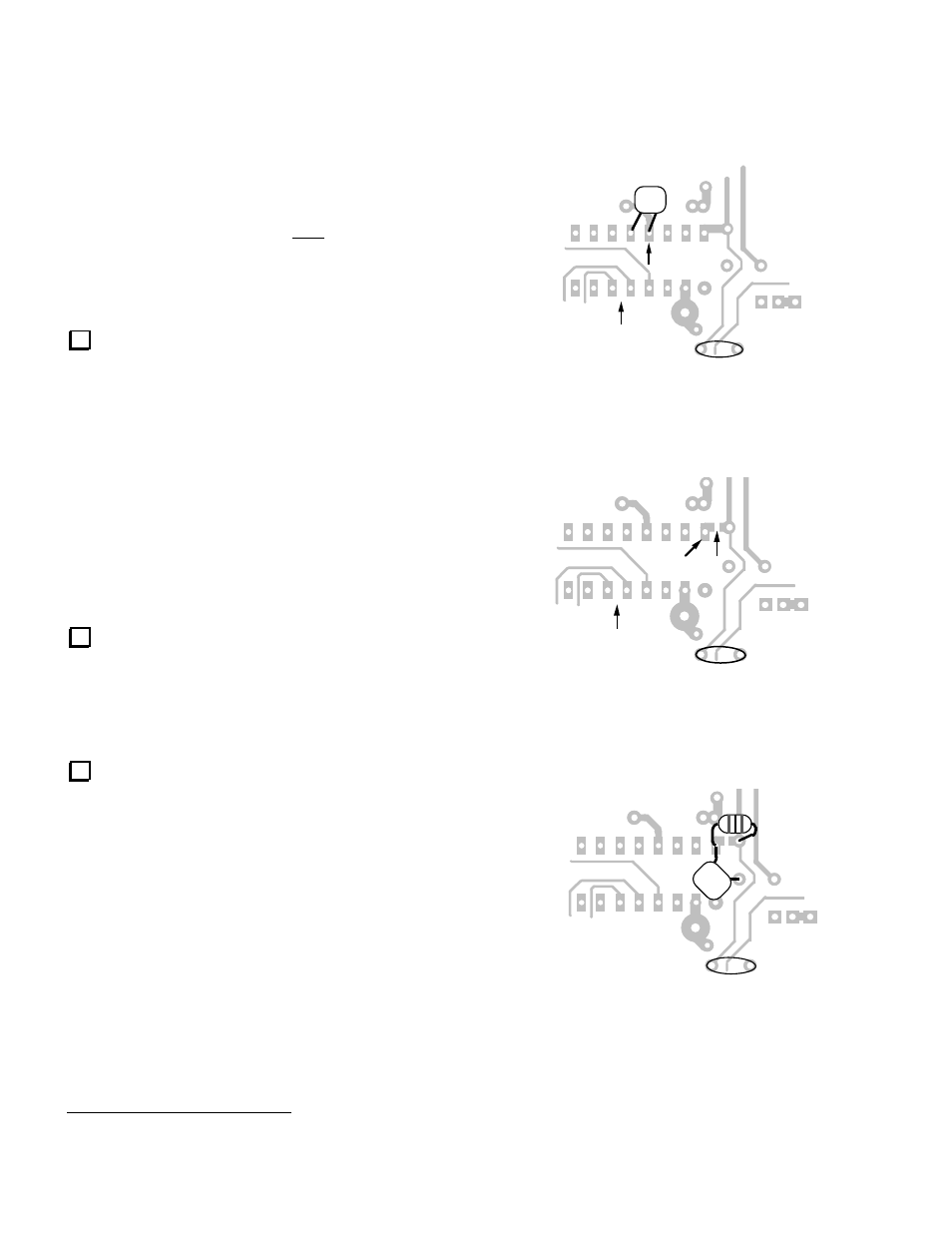
Solder a 68-pF capacitor (RF-C
PLL
) on the bottom of the
RF board, between pins 13 and 12 of the MC145170,
U4 (see Figure 1). Keep the lead length short.
Add an RF choke in series with U4 pin 16. First locate
point "X" in Figure 2. Cut the indicated small trace
segment between pin 16 of U4 and capacitor C89 (on
the top side). Next, solder a miniature 100-µH RF choke
(RFC15) across the cut as shown in Figure 3. Finally,
solder a.001-µF capacitor (C91) from pin 16 to ground.
Remove C70 (4.7 pF).
5
Due to differences in the way old and new firmware did
CAL PLL.
C90
MC145170
(bottom view)
Pin 13
Figure 1
C90
X
MC145170
(bottom view)
Pin 16
Figure 2
C90
C91
RFC15
Figure 3