Wiring the breakout board – Dynojet 224x: Installation Guide User Manual
Page 33
I N S T A L L A T I O N
Cable Routing
Version 4
Above Ground Model 224 Automotive Dynamometer Installation Guide
2-13
W
IRING
THE
B
REAKOUT
B
OARD
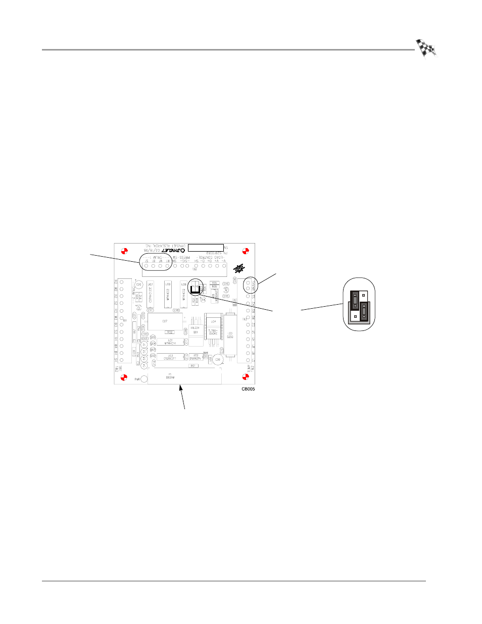
1
Attach the pickup card cable to the Breakout board. This cable may already be
connected.
The pickup card cable has four wires which connect to the wiring block labeled
DRUM 1.
2
Attach the brake solenoid cable to the Breakout board. The brake signal cable has
two wires which connect to the wiring block labeled BRAKE.
3
Attach the 25-pin cable from the dyno electronics to the Breakout board location
as shown in Figure 2-10.
4
Verify the jumpers are set as shown in Figure 2-10.
Figure 2-10: Wiring the Breakout Board
• Red wire connects to R1
• Black wire connects to B1
• White wire connects to W1
• Ground (shield) wire connects to S1
jumpers
J1 and J2
digital brake
jumper settings
pickup card
brake signal
J1 J2
25-pin dyno electronics
cable