Dyno electronics – Dynojet 224x: Installation Guide User Manual
Page 19
S P E C I F I C A T I O N S A N D O P E R A T I N G R E Q U I R E M E N T S
Dyno Electronics
Version 4
Above Ground Model 224 Automotive Dynamometer Installation Guide
1-9
. . . . . . . . . . . . . . . . . . . . . . . . . . . . . . . . . . .
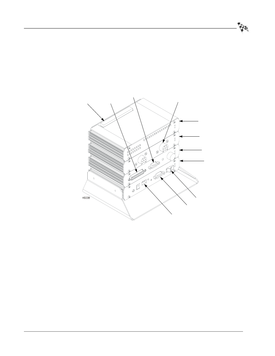
DYNO ELECTRONICS
The standard dyno electronics package is comprised of four interconnected modules.
Use the figure below to identify the modules and connectors when routing cables. A
detailed description of each module along with the instructions for connecting the
dyno electronics to the WinPEP 7 software can be found in your WinPEP 7 User Guide.
Figure 1-3: Dyno Electronics
9-pin RS-232 socket
CPU module
atmospheric
sensing module
RPM module
input/output module
9-pin hand
held pendant
3-pin power plug
system expansion
connector
inductive pickup
socket
25-pin socket
power