Installing the interface guide – Dynojet 224x: Installation Guide User Manual
Page 27
I N S T A L L A T I O N
Dyno Installation
Version 4
Above Ground Model 224 Automotive Dynamometer Installation Guide
2-7
I
NSTALLING
THE
I
NTERFACE
G
UIDE
The interface guide secures the dyno to the four-post lift. It is a good idea to install
your interface guide before anchoring your dyno to the ground. If you have the
interface roller assembly instead of the interface guide, refer to Appendix C.
You will need the following parts:
• 21600000
Interface Bar
• 21600001
Interface Bracket
secured to the dyno using P/N 36582471 Bolt, 3/8-16 x 1.5",
Flange-Hex (2)
• 36488100
Nut, 3/8-16, Nylock (2)
• 36500000
Bolt, 3/8-16 x 4.5", Hex, Full Thread (2)
• 36923100
Washer, 3/8", Hardened, Flat, Steel (4)
• 61100000
Interface Guide
1
Raise the lift until the bottom of the lift is approximately 86.36 cm (34.00 in.)
above the floor.
2
Loosely attach the interface guide to the lift cross member using two
3/8 x 4.5-inch bolts, four 3/8-inch flat washers, and two 3/8-inch nylock nuts.
Note: Verify the interface guide with the pin is facing the dyno and is near the
bottom of the lift cross member.
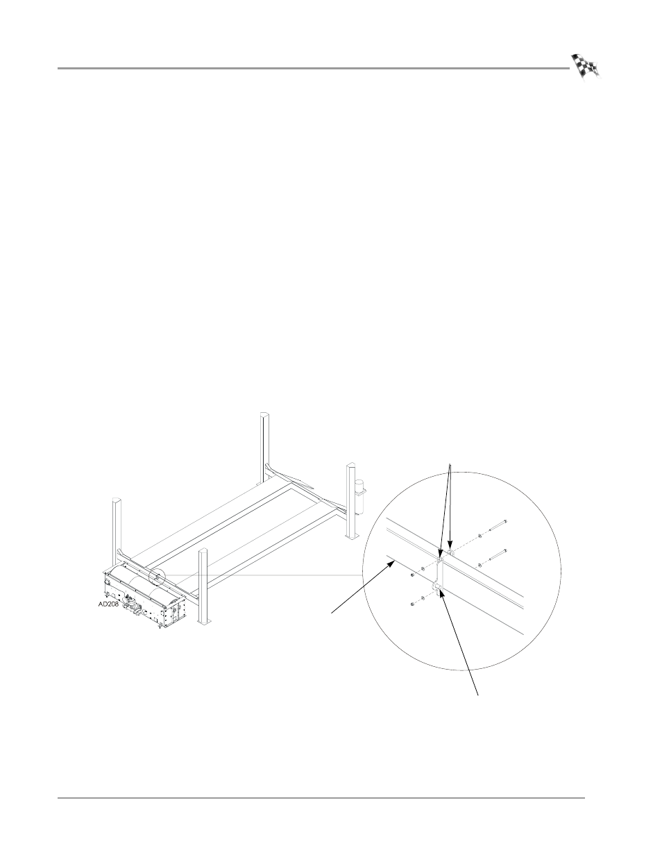
Figure 2-4: Interface Guide and Lift Cross Member
lift cross
member
interface guide with the pin facing
the dyno and near the bottom of
the lift cross member
interface guide