Dynojet 250iP: Pit Installation Guide User Manual
Page 31
I N S T A L L A T I O N
Eddy Current Brake
Version 2
Model 200iP/250iP Motorcycle Pit Dynamometer Installation Guide
2-11
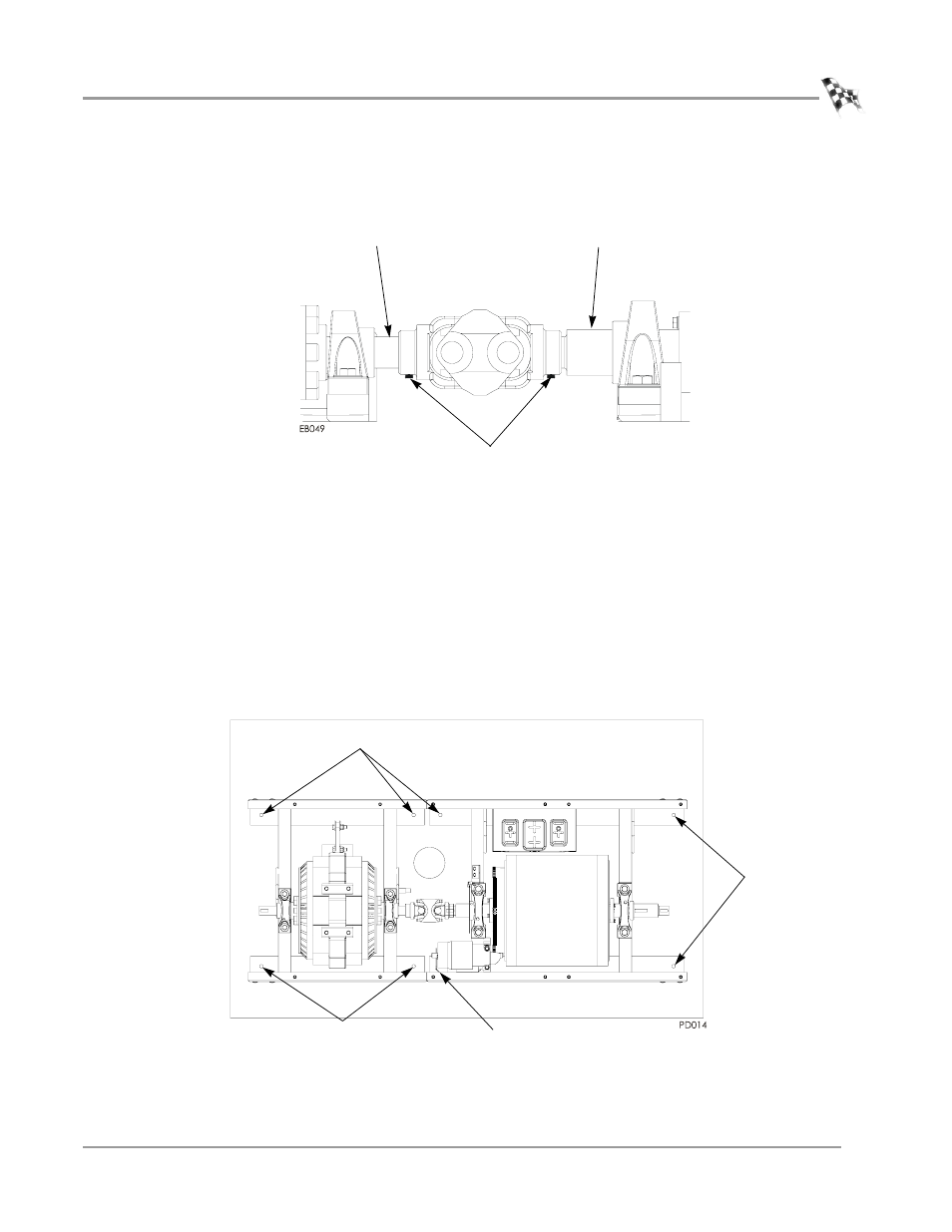
11 Replace the existing set screws on the coupler with the thread-lock set screws
provided.
12 Tighten the coupler set screws.
Figure 2-11: Tighten the Set Screws
S
ECURING
THE
D
RUM
AND
B
RAKE
M
ODULE
TO
THE
P
IT
F
LOOR
Dynojet recommends you secure your drum and brake modules to the pit floor in
your dyno room using concrete anchors. You will want to drill the holes and secure
the dyno before placing the covers on your dyno.
Note: You may wish to drill the holes for the carriage mounting plate, blower
mounts, and the support arm at this time. Refer to page 2-13 for carriage plate
instructions and page 2-16 for blower mounts and support arm instructions.
1
Drill the holes for Red Head Anchors.
2
Install the Red Head anchors according to the instructions in Appendix A.
Figure 2-12: Secure the Drum and Brake Module to Pit Floor
brake shaft
dyno shaft
set screw
drill holes
drill hole (not visible) only when brake is mounted on right side
drill holes
drill holes