Dynojet 250iP: Pit Installation Guide User Manual
Page 30
Model 200iP/250iP Motorcycle Pit Dynamometer Installation Guide
C H A P T E R 2
Eddy Current Brake
2-10
6
Continue sliding the eddy current brake towards the dyno until the uprights on
the brake and dyno are flush.
7
Loosely secure the retarder connector plates to the dyno frame using the eight
bolts, washers, and six nuts removed earlier.
Note: Do not tighten the bolts.
8
Verify the uprights on the drum and eddy current brake modules are flush with
the top of the pit floor before you tighten the connector plates.
8a
Loosen all upright bolts.
8b
Place two straight edges across the drum module uprights as shown.
8c
With the upright tight against the straight edges, tighten the connector plate
bolts and nuts on the drum module.
Note: You can use c-clamps to attach the upright to the straight edges to make
this quicker. Tighten the c-clamps until the uprights are flush with the pit floor.
8d
Tighten the upright bolts and nuts on the drum module.
8e
Repeat this for the eddy current brake module uprights.
9
Secure the starter brace to the starter using the washer and nut removed earlier.
10 Remove the straight edges.
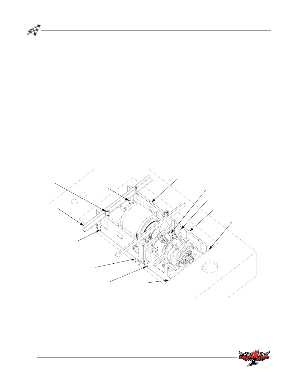
Figure 2-10: Secure the Uprights
PD009A
straight edge
c-clamp
starter brace
drum module
upright
eddy current brake
module upright
loosen bolts
securing
uprights
loosen bolts
securing uprights
(not visible)
loosen bolts
securing uprights
(not visible)
loosen bolts
securing
uprights
loosen bolts
securing
uprights
connector
plate bolts
connector plate bolts