Installing a server module, Hard drives/ssds – Dell PowerEdge M820 (for PE VRTX) User Manual
Page 30
3.
slots on the chassis (4)
Installing a server module
NOTE: Ensure that you remove the server module partitions before installing the M820 server
module. For information about removing the server module partitions, see Dell PowerEdge VRTX
Enclosure Owner’s Manual at dell.com/poweredgemanuals.
1.
If you are installing a new server module, remove the plastic cover from the I/O connector(s) and
save for future use.
2. Orient the server module so that the handle is on the left side of the server module.
3. Align the server module with the server module slot and the guide rails on the enclosure.
4. Using both hands, slide the server module into the enclosure until the module release handle
engages and locks the server module in place.
5. If applicable, reinstall the front bezel.
Hard drives/SSDs
• The system supports up to four 2.5 inch SAS hard drives/PCIe SSDs.
• All drives connect to the system board through the SSD/SAS hard-drive backplane.
• Hard drives/PCIe SSDs are supplied in special hot-swappable drive carriers that fit in the drive slots.
• All empty drive slots must have hard-drive blanks installed.
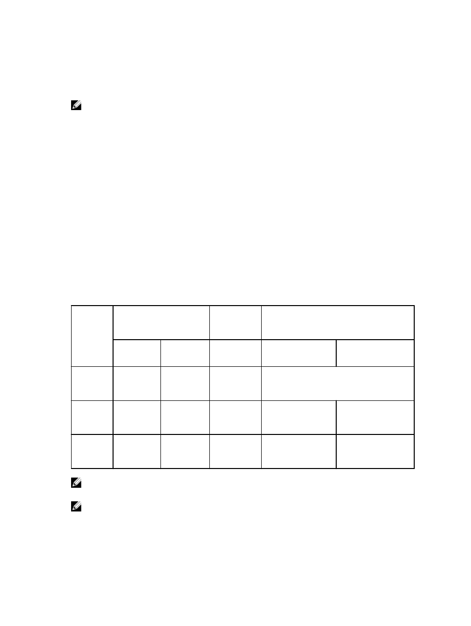
The following table lists the supported hard drive/SSD configurations.
Table 1. Supported hard-drive/controller card/drive backplane configurations
Number of
Drives
Drive Population
Storage
Controller
Card Type
Installed
Drive Backplane Installed
Drive Bay 0
Drive Bay 1
MiniPERC
CARD
Connector
System Board
Backplane
Connector J_BP0
System Board
Backplane
Connector J_BP1
Four
Two SAS
hard drives
Two SAS
hard drives
Storage
controller
card
SAS drive backplane with four drive slots
Four
Two SAS
hard drives
Two PCIe
SSDs
Storage
controller
card
SAS hard-drive
backplane with two
drive slots
PCIe SSD backplane
with two drive slots
Two
Two SAS
hard drives
-
Storage
controller
card
SAS hard-drive
backplane with two
drive slots
-
NOTE: The SAS drive backplane with four drive slots is installed on the system board connectors
labeled J_BP0 and J_BP1.
NOTE: SAS hard-drive backplane (with two drive slots) for drives installed in drive bay 0 is installed
on the system board connector labeled J_BP0. The SSD backplane (with two drive slots) for PCIe
SSDs is installed on the system board connector labeled J_BP1.
30