Canon GALVANO GC-251 User Manual
Page 45
CANON Digital Galvano Scanner System
KP-1SM Series + GC-251
Users Manual 1.00
45
5.3.
Digital Input-Output Function
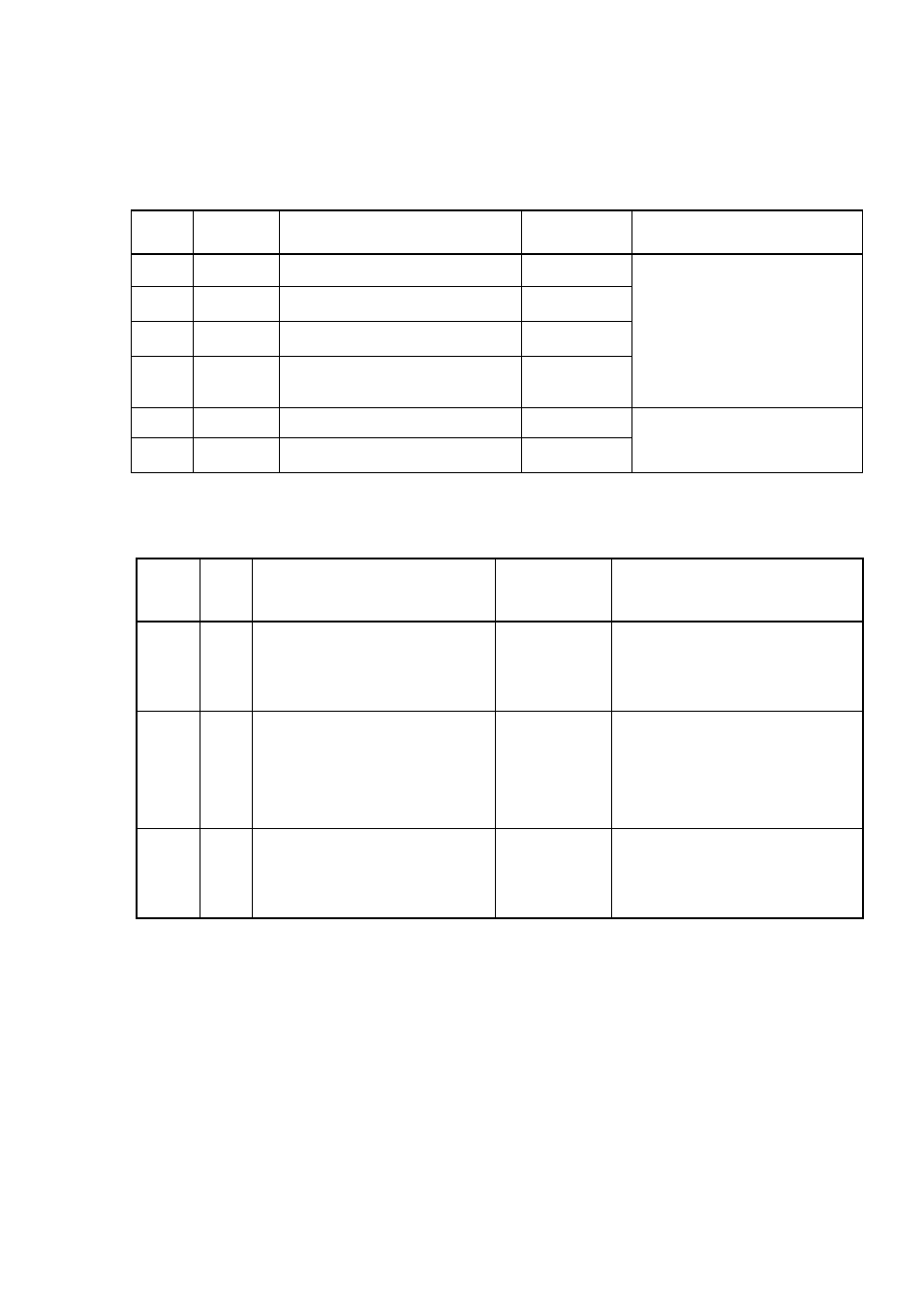
The controller has a digital input-output function for checking the status of the controller.
Pin
No.
I/O Signal
Description Logic
Explanation
A1
Output
Axis 1 Error 1 (Priority high)
1:
Error
If an error occurs, the
corresponding error signal is
output.
According to the priority of the
error, Error 1 or 2 is output.
See 9-2, “Errors.”
B1
Output
Axis 1 Error 2 (Priority low)
1: Error
B2
Output
Axis 2 Error 1 (Priority high)
1: Error
A3
Output
Axis 2 Error 2 (Priority low)
1: Error
A2
Output
Axis 1 servo interrupt period
Edge
These are output at a servo
interrupt timing in the
controller.
B3
Output
Axis 2 servo interrupt period
Edge
In addition, the following, digital I/O is prepared as an operation setting of the controller.
Pin
NO.
I/O Signal
Description
Logic
Explanation
A5
Input External Sampling Signal
INT
generation
When external signal is used for
servo sampling clock.
(Do not use it usually.)
B5 Input
External
Trigger
Signal
High ON
See 6-2, “Operation that
synchronizes with external
trigger Signal input(raster scan)
A6
Input Activation mode switching
See 6-1, “Setting Controller
Activation Mode”