Indoor trim housing installation, Wiring the trims – Edge Lighting Miniport LED Components User Manual
Page 3
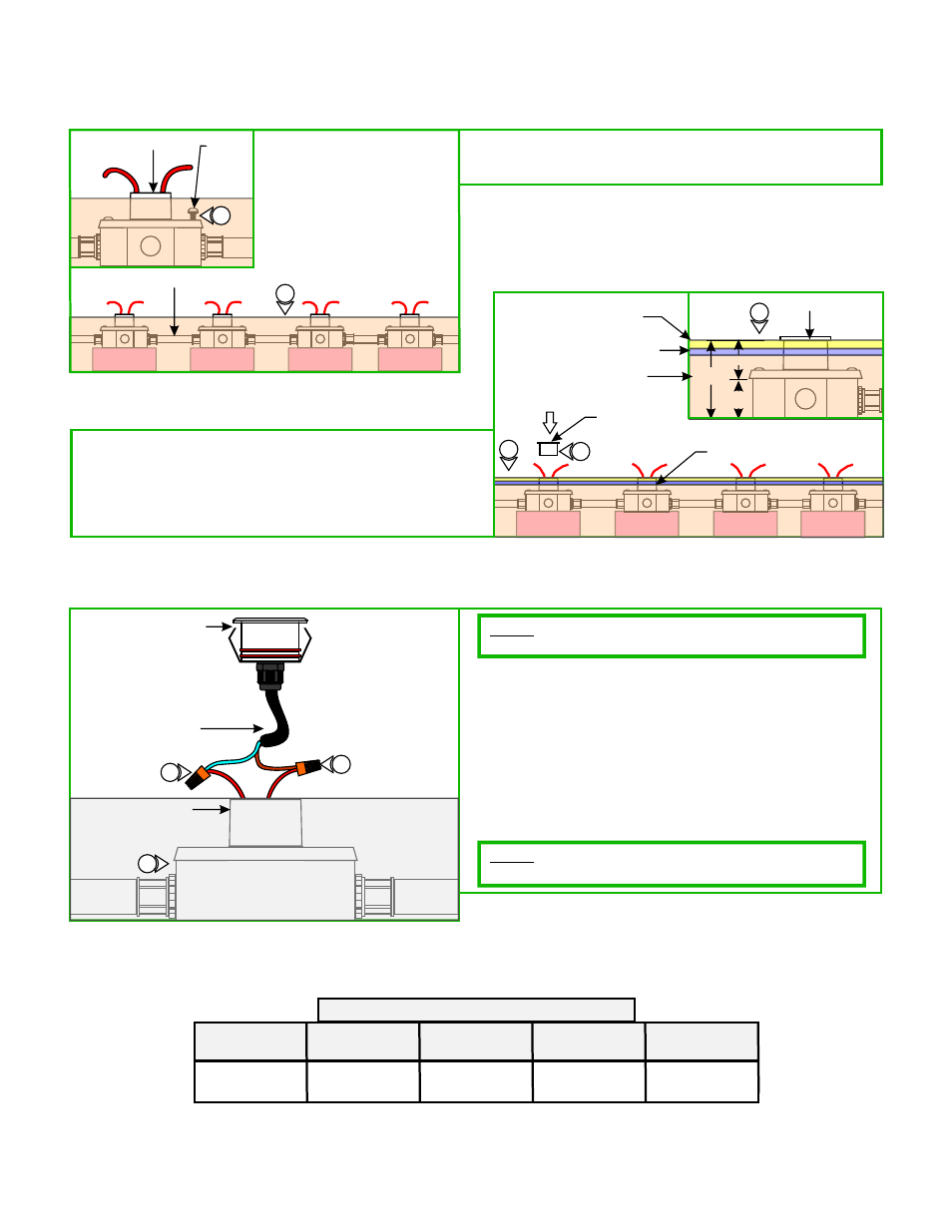
Indoor Trim Housing
Installation
2: Insert the provided plastic caps to all trim housing to prevent
dust and debris from entering inside the box.
3: Finish the floor installation up to the plastic cap.
4: Refer to the "Install the Trims" section.
1: Align and secure the each trim housing to the octagon
electrical box holes with the two #8-32 screws (not
provided).
12VAC
G
TRIM HOUSING #8-32
SCREW
CONDUIT
1
1
12VAC
12VAC
12VAC
H
PLASTIC
CAP
PLASTIC CAP
3
TRIM HOUSING
FLOOR
3
2.97"
1.5"
1.47"
2
JOIST
SUBFLOOR
I
TRIM
NOTE:
Miniport consumes 1 watt.
Each fixture contains an integrated LED lamp. Each
Wiring the Trims
1: Remove the plastic caps.
2: Connect the brown driver wire to one low voltage wire
(either one) and the blue driver wire to the other low voltage
wire coming from the transformer with wire nuts.
3: Place all wire connections inside the electrical box and push
the trim completely into the trim housing opening.
4: Repeat steps 1 through 3 for other trims.
NOTE:
nuts for power connection.
For outdoor installation, use water proof outdoor wire
2
2
LED
DRIVER
6
TRIM
HOUSING
3
LOW VOLTAGE WIRE SIZE CHART
TRANSFORMER
WATTAGE
WIRE SIZE
FOR UP TO 13 FT
WIRE SIZE
FOR 14-20 FT
WIRE SIZE
FOR 21-34 FT
WIRE SIZE
FOR 34-52 FT
12V 60W
TE-60L-12
#14 AWG
#12 AWG
#10 AWG
#8 AWG