Outdoor trim housing installation – Edge Lighting Miniport LED Components User Manual
Page 2
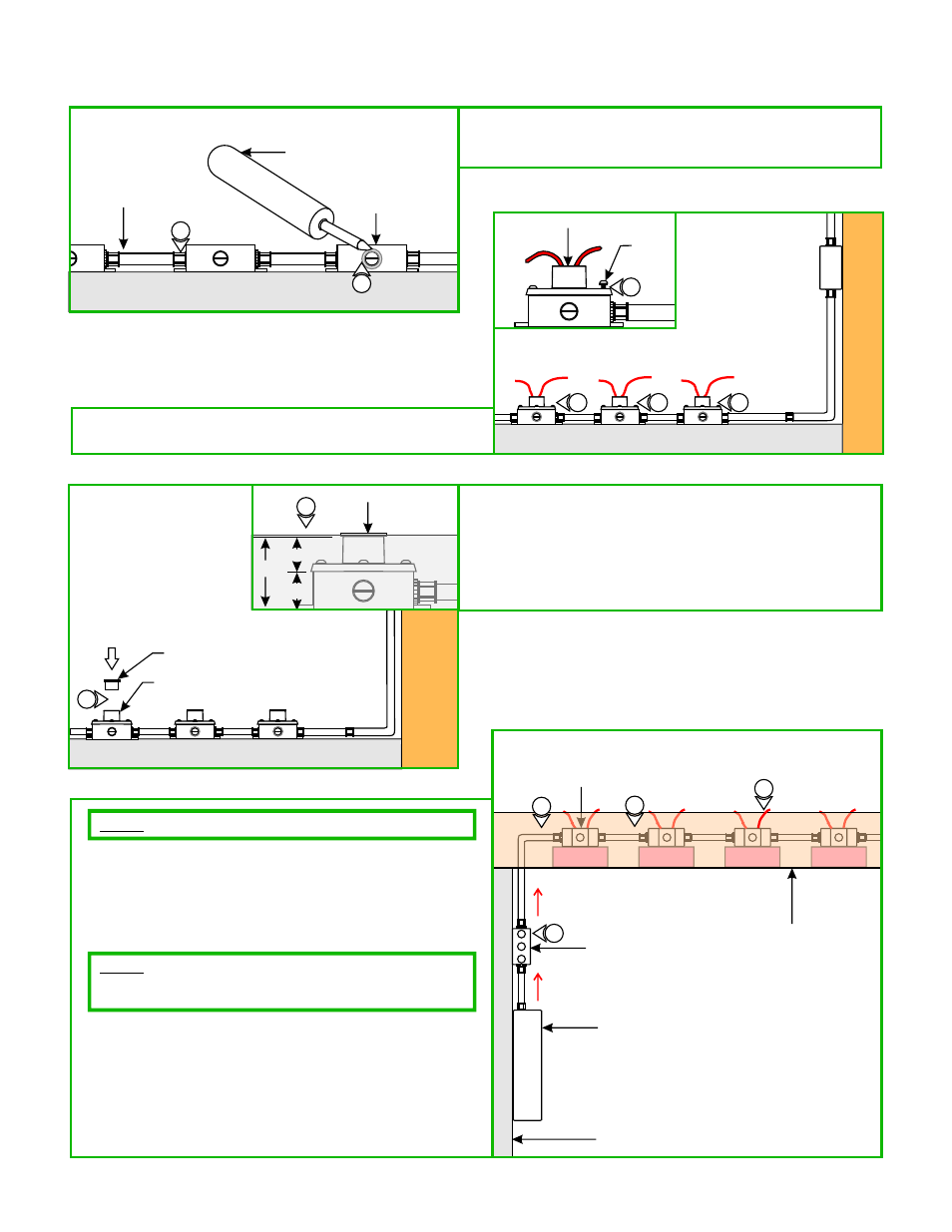
2
GROUND
D
TRIM HOUSING
#10-24
SCREW
2
2
2
2
2: Align and secure each trim housing to the electrical box holes
with the four #10-24 water sealant screws provided.
E
3: Insert the provided plastic caps to all trim housings to
prevent particles and concrete debris from entering inside
the box.
4: Poor the concrete up to plastic cap and wait to dry.
5: Refer to the "Install the Trims" section.
PLASTIC CAP
4
2.97"
1.5"
1.47"
CONCRETE
TRIM HOUSING
PLASTIC CAP
3
GROUND
C
1: Caulk all areas of the outdoor electrical boxes and the
conduit connectors with a water proof silicone to prevent
water entering in the electrical boxes.
OUTDOOR
ELECTRICAL BOX
OUTDOOR
CONDUIT
WATER PROOF
SILICONE
GROUND
1
1
Outdoor Trim Housing Installation
12VAC
12VAC
12VAC
F
PANEL
OCTAGON ELECTRICAL BOX
1
WALL
BRANCH ELECTRICAL BOX
12VAC
120VAC
4
2
3
JOIST
NOTE:
Use only octagon boxes to install the trim housings indoor.
1: Install an electrical box onto the wall or post next to the
panel to fit the LED power supply (TE-60L-12) and to branch
the power to all octagon electrical boxes.
2: Install conduit and run 120 volt power wires from the panel
to the branching electrical box.
3: Install conduit(s) from the branching electrical box to all
octagon fixture electrical boxes.
4: Run proper wire sizes from branching electrical box to all
fixture electrical boxes using the "Wire Size Chart" on page 3.
5: Follow steps 5 through 8 on page 1 using drawing B to
connect the wires to the power supply.
NOTE:
must be considered when positioning the octagon boxes between
the joists.
Subfloor, floor, and Miniport trim housings (1.47") heights
Indoor Installation Using a Single
LED Power Supply (TE-60L-12)