Edge Lighting Cirrus Channel, Tubular 1" Lens User Manual
Connecting the channel, Important information, Save these instructions
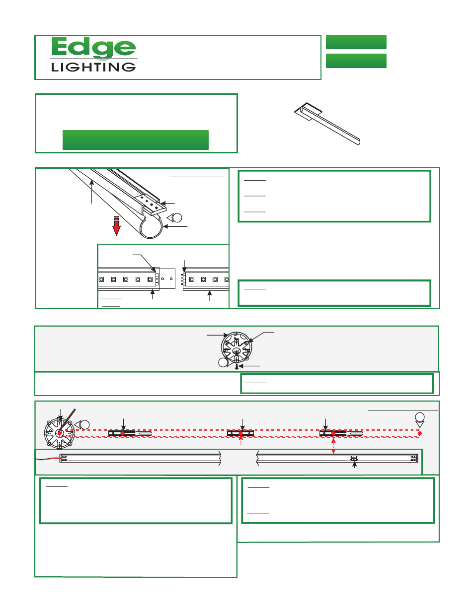
JOINER BRACKET
1
LENS
JOINER CHANNEL
MALE
CONNECTOR
FEMALE
CONNECTOR
CHANNEL
FRONT
VIEW
TOP OF CHANNEL
A
CHANNEL
Installation Instructions for Cirrus Channel T1, Tubular 1" 24VDC
904-CC-T1-02
1718 W. Fullerton Ave
Chicago, IL 60614
Tel: 773-770-1195
Fax: 773-935-5613
www.edgelighting.com
© 2013 Edge Lighting. All Rights Reserved.
CC-T1-2WDC-_
CC-T1-5WDC-_
1: Lift a section of the lens at the end of the channels where
the connectors are visible. Slide the channel over the joiner
bracket make sure that the male & female connectors mate
properly.
2: Push the lens back into the channel.
Connecting the Channel
NOTE:
(C-1RE-BOX), continue to "Install the Channel using the Junction
Box (C-1RE-JBOX)" on page 3.
When using Edge Lighting Slim Profile Junction Box
B
#8-32 SCREW
CROSSBAR
JUNCTION BOX
1
SAVE THESE INSTRUCTIONS!
- This instruction shows a typical installation.
- Per NEC Article 410.16(A)(1)(3) & 410.16(C)(5). Approved
for Closet Storage Areas.
IMPORTANT INFORMATION
NOTE:
piece (120" or less).
Omit this section if the channel is made out of a single
NOTE:
Prior to installation, multi-sectional Cirrus Channel should
be connected together for marking proper measurements.
NOTE:
It is recommended more than one person to assist in this
installation.
Install Channel on Standard Junction Box W/Plaster Ring or Octagon Box
1: Mount the crossbar to the Junction box holes with the two
#8-32 screws provided.
NOTE:
C-1RE-JBOX.
Omit this section and follow steps on Page 3 when using
C
CHANNEL END
BOTTOM OF CHANNEL
JUNCTION BOX
MOUNTING
CLIP (C-MCL)
RECEIVING BRACKET
MARKING LOCATION
LOCKING CLIP
3
NOTE:
Remote power supply must be installed within 40ft of
Junction box. The low voltage 24V DC wires must be present in
Junction box before installing the channel. Refer to the
installation instructions provided with the power supply. See
page 5 for wiring diagram.
NOTE:
If the receiving bracket interferes with the Junction box
or wires, then relocate the receiving bracket by loosening the
screws and make the necessary adjustments.
NOTE:
The channel must pass through the center of the
Junction box.
EVERY 20 INCHES
2:
B
egin installation using side of the channel with power wire.
Lay channel to the desired location & make all necessary
markings which will consist of the channel ends, locking clips
and mounting clips. Mounting clips must be installed 20"
from each other. Locking clips are not necessary for
channels under 2ft.
3: After all markings and required measurements are done,
take the channels apart from each other.
1
2
LOCKING CLIP