Cooper Instruments & Systems DFI Infinity CS Economy Digital Indicator User Manual
Page 9
DFI INFINITY CS (V- M3598/N/0906)
6
CF 70
Table 2-2 Connector Description
Connector Description
TB1-1
TB1-2
TB1-3
TB1-4
TB1-5
TB1-6
TB1-7
TB1-8
TB1-9
TB1-10
TB1-11
TB1-12
Setpoint 1: Normally open (N.O.1) connection
Setpoint 1: Normally closed (N.C.1) connection
Setpoint 1: Common (COM1) connection
Setpoint 2: Normally open (N.O.2) connection
Setpoint 2: Normally closed (N.C.2) connection
Setpoint 2: Common (COM2) connection
AC line connection (no connections on DC-powered units)
AC neutral connection (+ Input on DC-powered units)
AC earth ground (DC-power return on DC-powered units)
Analog voltage output
Analog current output
Analog return
TB2-1
TB2-2
TB2-3
TB2-4
TB2-5
TB2-6
TB2-7
TB2-8
-E: Negative excitation connection from meter (5,10,12 V)
+E: Positive excitation connection from meter (5,10,12 V)
+20 mA connection for analog input
+R (Not used)
+24 V output connection
+S: Positive signal input
-S: Negative signal input and return for +20 mA or +24 V
-R (Not used)
TB5-1
TB5-2
TB5-3
Isolated Analog Voltage Output
Isolated Analog Current Output
Isolated Analog Output Return
J1 (1-2)
Remote tare connection with a momentary switch
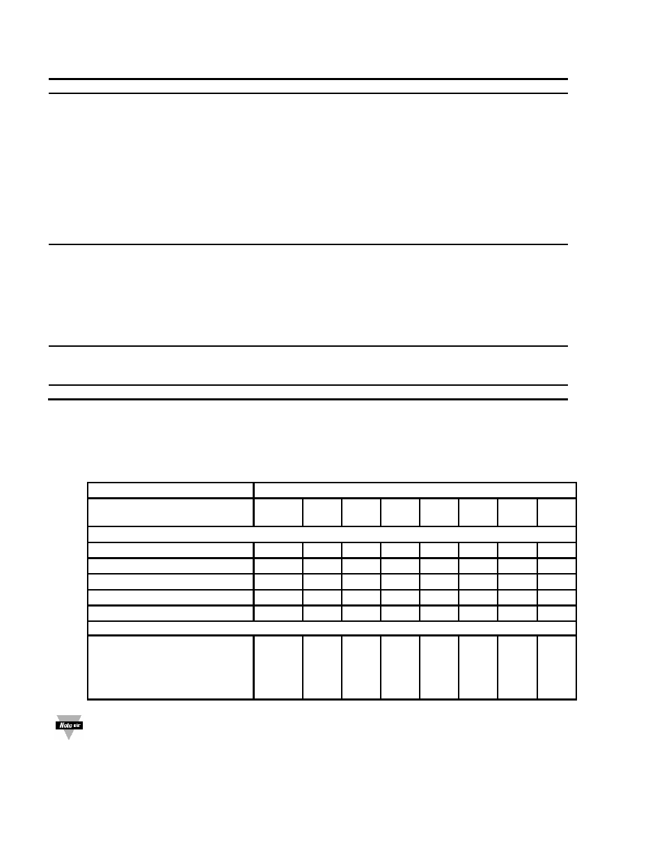
The DIP switches are located at the S1 position (Refer to Figure 3-2). Use a small instrument such as a paper clip
to change the switches from open to closed. Table 2-3 lists DIP switch settings at the S1 position required to
complete the setup of your meter.
Table 2-3 DIP Switch Positions/Input Range & Excitation
Function
S1 DIP Switch Positions
C= Closed
O= Open
1 2 3 4 5 6 7 8
Settings for Excitation Voltage
Internal 5/10/12 excitation
C - - - - - - -
External 5/10/12 excitation
O - - - - O O -
Internal 12 Vdc Excitation
C - - - - O O -
Internal 10 Vdc Excitation
C - - - - C O -
Internal 5 Vdc Excitation
C - - - - C C -
Settings for Input Ranges
0-100 mV dc
±50 mV dc
±5 Vdc
0-10 Vdc
0-20 mA dc
-
-
-
-
-
O
O
C
C
O
C
C
O
O
C
O
O
O
O
C
O
C
C
O
O
-
-
-
-
-
-
-
-
-
-
O
O
C
C
O
The display must also be configured to the selected input type after setting the DIP switches (see Section
4.1, Selecting the Input Type)
2.6 Disassembly
You may need to open up the meter for one of the following reasons: