Cooper Instruments & Systems DFI Infinity CS Economy Digital Indicator User Manual
Page 13
DFI INFINITY CS (V- M3598/N/0906)
10
CF 70
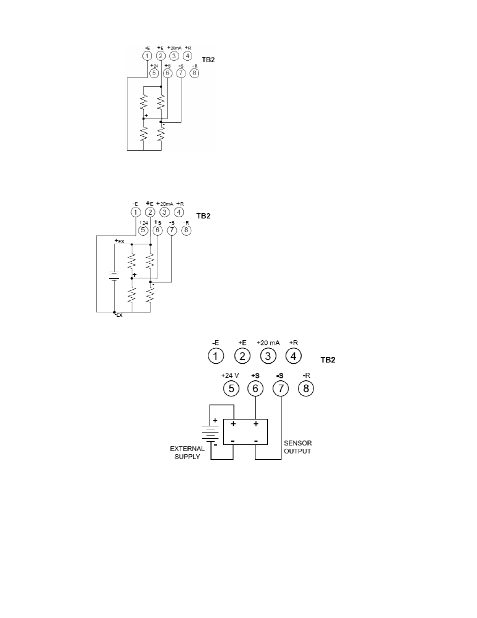
Connections with ”typical wire colors”
+E = Positive Excitation (red)
-E = Negative Excitation (black)
+S = Positive Signal Input (green)
-S = Negative Signal Input (white)
Figure 3-6 Meter-powered Bridge Input
Figure 3-7 shows the connections required for an externally-powered bridge input: the external supply is brought to
the meter’s buffer circuits to permit ratiometric readings. Set S1 DIP switch for external excitation for Figure 3-7
and 3-8.
Connections with ”typical wire colors”
+E = Positive Excitation (red)
-E = Negative Excitation (black)
+S = Positive Signal Input (green)
-S = Negative Signal Input (white)
Figure 3-7 Externally-powered Bridge Input
Figure 3-8 4-Wire DC Input Connections with External Excitation