Cooper Instruments & Systems DFI Infinity CS Economy Digital Indicator User Manual
Page 12
DFI INFINITY CS (V- M3598/N/0906)
9
CF 70
Table 3-1 S3 Jumper Functions
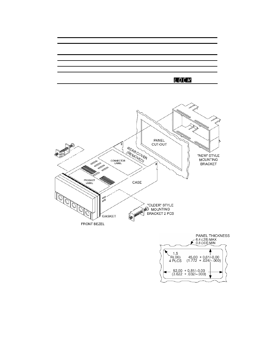
3.3 Panel Mounting
Figure 3-4 Meter – Exploded View
1. Cut a hole in your panel, as shown in Figure 3-4. For
specific dimensions refer to Figure 3-5.
2. Insert the meter into the hole. Be sure the front bezel
gasket is flush to the panel.
3. Slide on mounting bracket to secure.
4. Proceed
to
Section 3.4 to connect your sensor input
and main power.
NOTE: Dimensions in Millimeters (Inches)
Figure 3-5 Panel Cut Out
3.4 Connecting Sensor Inputs
Figure 3-6 shows excitation supplied from the meter’s internal supply (50mA maximum). Select 5,10, or 12 volt
excitation at DIP switch.
Jumper Description
S3-A
Install to enable front panel push buttons.
Remove to disable all front panel push-buttons
S3-B
Removed. For factory calibration only.
S3-C
Removed. Not Used
S3-D
Installed for external ratiometric.
S3-E
If installed without S3-B, the MENU button locks out. If you
press the MENU button, the meter shows
.