Cooper Instruments & Systems DFI 1650 Multi-Channel Digital Force Indicator User Manual
Page 56
CF 66
50
Rev. C 2/05
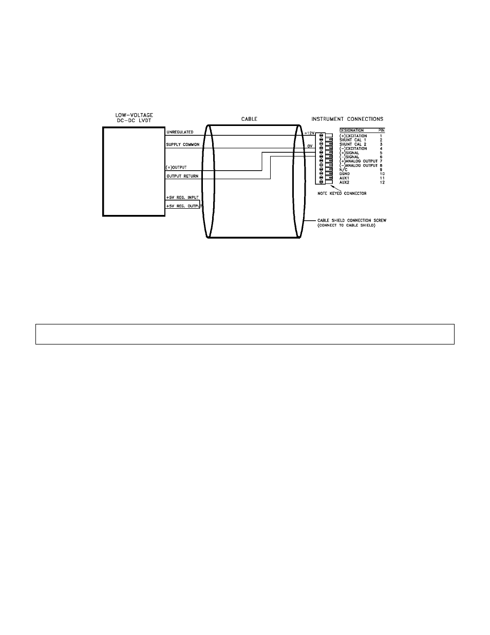
The High-Level Input channel’s Configuration Jumpers must be set as follows for proper operation. See “Excitation
and Signal Jumpers” in Section 12.3.
• (+)Excitation supply: “+12 VDC”
• (-)Excitation supply: “GND”
• Signal type: “voltage”
• Signal reference: “single ended”
Figure 12-7: “Low Voltage” DC-DC LVDT Connection to High-Level Input Channel
12.3 Excitation and Signal Jumpers
12.3.1 Overview
The High-Level Input channel has hardware jumpers which allows configuration of excitation supply voltages and
signal inputs to match the wide variety of amplified pressure, load and DC-DC LVDT transducers produced by
Cooper. “Wiring” explains which jumpers settings are required for a particular transducer.
Make certain that you are setting the jumpers correctly. Incorrect placement of the Excitation and Signal jumpers
can damage both the transducer and the instrument.
12.3.2 Setting Jumpers
Step 1: Find the “Case Removal” section in Chapter 4 “Chassis Models” that matches the particular chassis model.
Follow the directions and remove the rear panel.
Step 2: Remove the channel board from the chassis.
Step 3: Change the jumper settings according to the figure below. Note that there are two separate jumpers for
the “signal type”; both must match.
Step 4: Re-install the channel board and replace the rear panel.