Cooper Instruments & Systems DFI 1650 Multi-Channel Digital Force Indicator User Manual
Page 54
CF 66
48
Rev. C 2/05
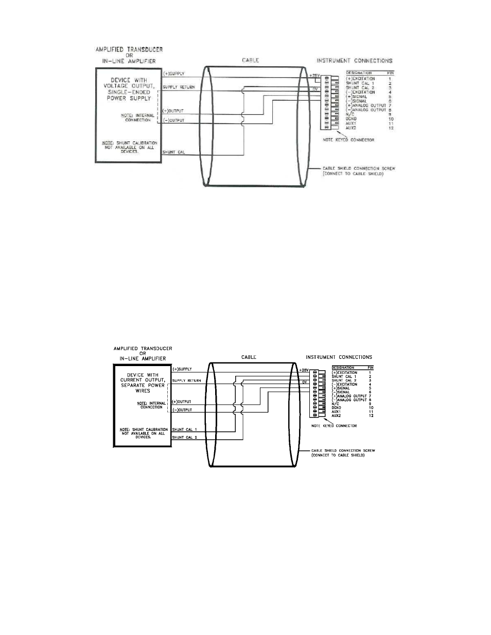
Figure 12-3: “3-wire Voltage Amp w/Single-Wire Shunt Cal” Connection to High-Level Input Channel
12.2.5 “3-wire Current” Amplifiers
Use the following wiring diagram when connecting an amplified transducer or in-line amplifier with a 3-wire current
amplifier to a High-Level Input channel. Examples of such devices include:
• transducers with the Option 2j internal amplifier (with shunt cal)
• Model U3W Universal In-Line amplifiers (with shunt cal)
The High-Level Input channel’s Configuration Jumpers must be set as follow for proper operation. See “Excitation
and Signal Jumpers”.
• (+)Excitation supply: “+28 VDC”
• (-)Excitation supply: “GND”
• Signal type: “voltage”
• Signal reference: “single-ended”
Figure 12-4: “3-wire Current Amp” Connection to High-Level Input Channel
12.2.6 “2-wire Current” Amplifiers with Buffered Shunt Cal
Use the following wiring diagram when connecting an amplified transducer or in-line amplifier with a 2-wire current
amplifier to a High-Level Input channel. Examples of such devices include:
• transducers with the Option 2k internal amplifier (not equipped with shunt cal)
• transducers with the Option 2k, 3d internal amplifier (buffered shunt cal)
• Model U2W Universal In-Line amplifiers (not equipped with shunt cal)
The High-Level Input channel’s Configuration Jumpers must be set as follows for proper operation. See “Excitation
and Signal Jumpers” in section 12.3.