Cooper Instruments & Systems DFI 1650 Multi-Channel Digital Force Indicator User Manual
Page 21
CF 66
15
Rev. C 2/05
5.3 Function Input Pins
5.3.1 Overview
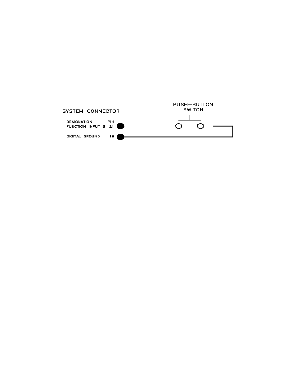
To use a Function Input pin (9, 10, 11 or 21), connect it to the DGND (pin 19) momentarily. This can be
accomplished by a push button switch, relay contact closure, or PLC output.
Usually, the Function Input pins perform the default actions described in the “System Connector Pinout”. However,
a SensoCode program running on a Mathematics Virtual Channel may replace these default actions. Consult the
System Calibration Sheet included with your instrument for details.
5.3.2 Example
For example, assume that you wish to use Function Input #3 to tare all channels in the instrument simultaneously.
Connect a push-button switch as shown below.
Figure 5-1: Function Input Example
5.4 Limit Output Pins
5.4.1 Overview
An open-collector output is a transistor logic output that can be used to control DC loads, drive opto-isolators or
relays, or interface directly to logic circuitry. They act very much like switches: low resistance when turned on and
high resistance when turned off. You can used them as you would a dry relay contact, with the following
restrictions:
• The voltage applied must be DC
• The polarity of the DC voltage must be observed
• Maximum voltage: 50VDC
• Maximum power: 2.0W
When Limits 1, 2, 3, or 4 are activated, the corresponding open-collector Limit Output pin on the System connector
will be connected to the DGND (Digital Ground) pin. However, a SensoCode program running on a Mathematics
Virtual Channel may override this behavior. Consult the System Calibration Sheet included with your instrument for
details.
5.4.2 Example
For example, assume that a remote indicator is to be lighted when Limit 1 is activated. An external 24 VDC power
supply connects to the indicator.
When Limit 1 is deactivated, there is high resistance between the Limit 1 Output pin and the DGND (Digital Ground)
pin; little current flows in the circuit and the light is off. When Limit 1 is activated, there is low resistance between
the Limit 1 Output pin and the DGND (Digital Ground) pin; the light turns on.
The resistor limits the current flowing in the circuit when the light is lighted to 48mA. According to Ohm’s Law:
I=V/R
48mA=24V/500Ω
Lights or other indicators have voltage, current, and/or power ratings that must be observed in order to avoid
damaging them.