Cooper Instruments & Systems DFI 1650 Multi-Channel Digital Force Indicator User Manual
Page 53
CF 66
47
Rev. C 2/05
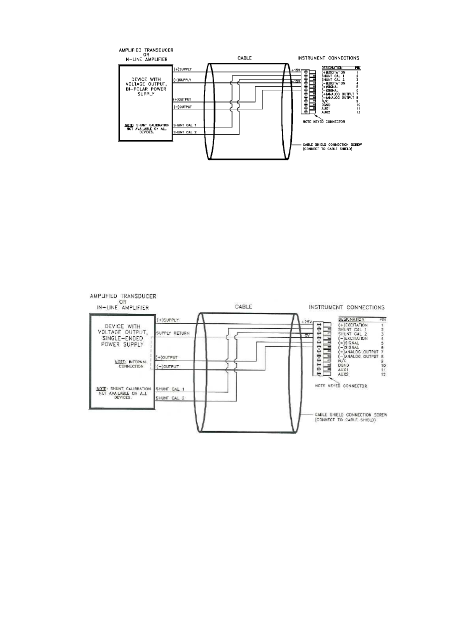
Figure 12-1: “Bi-polar Voltage Amp” connection to High-Level Input Channel
12.2.3 “3-wire Voltage” Amplifiers
Use the following wiring diagram when connecting an amplified transducer or in-line amplifier with 3-wire voltage
amplifier to a High-Level Input channel. Examples of such devices include:
• transducers with Option 2c or Option 2t internal amplifiers (with shunt cal)
• Models UV or UV-10 Universal In-Line amplifiers (with shunt cal)
The High-Level Input channel’s Configuration Jumpers must be set as follows for proper operation. See “Excitation
and Signal Jumpers”.
• (+)Excitation supply: “+28 VDC”
• (-)Excitation supply: “GND”
• Signal type: “voltage”
• Signal reference: “differential”
Figure 12-2: “3-wire Voltage Amp” Connection to High-Level Input Channel
12.2.4 “3-wire Voltage” Amplifiers with Single-wire Shunt Cal
Use the following wiring diagram when connecting an amplified transducer with 3-wire voltage amplifier to a High-
Level Input channel. An example of such a device includes:
• transducers with Option 2d or Option 2g internal amplifiers (with shunt cal)
The High-Level Input channel’s Configuration Jumpers must be set as follows for proper operation. See “Excitation
and Signal Jumpers”.
• (+)Excitation supply: “+28 VDC”
• (-)Excitation supply: “GND”
• Signal type: “voltage”
• Signal reference: “differential”