Cooper Instruments & Systems DFI 1650 Multi-Channel Digital Force Indicator User Manual
Page 19
CF 66
13
Rev. C 2/05
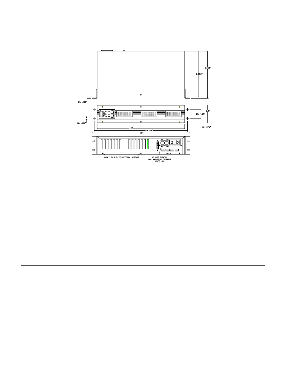
4.5 DFI SC3004
4.5.1 External Arrangement
Figure 4-5: External Arrangement of DFI SC3004
4.5.2 Rear Panel
The pinout for the 25-pin System connector is provided later in this chapter. The pinouts for the individual channels
are located in the chapter for that channel.
4.5.3 Panel Mounting
The panel space necessary conforms to the EIA 19” rack-mount standard. Panel mounting ears are attached to the
instrument.
4.5.4 Bench Mounting
Panel mounting ears are attached to the instrument, and may be removed if they are not needed.
4.5.5. Case Removal
Be sure to remove the power cord from the power source before attempting to remove the case from the
instrument.
Use a #0 Phillips screwdriver on all screws to avoid damaging them.
Step 1: Remove the four, silver rack-mounting ears from the left and right sides.
Step 2: Remove one Phillips screw from the top of the case.
Step 3: Remove two Phillips screws from the bottom of the black case cover.
Step 4: Remove the black case cover from the instrument.
Step 5: Remove eight Phillips screws from the rear panel, including the two cable shield connection screws.
NOTE: Do not remove the four screws that secure the cooling fan to the rear panel.
Step 6: Remove the rear panel.
4.5.6 Rear Panel
The pinout for the 25-pin System connector is provided later in this chapter.