Cooper Instruments & Systems DFI 1650 Multi-Channel Digital Force Indicator User Manual
Page 23
CF 66
17
Rev. C 2/05
Installing a channel will cause it to use the “default” or “empty” configuration information for that channel. Any
calibration data, SensoCode mathematics programs, display setup, or other information will be erased to default
values! All other channels are unaffected.
Input or Output Channel Installation Procedure
Before installing an Input or Output card, make certain that you know the “card type” (a two-digit hexadecimal
number) of the card you wish to install.
Use Electrostatic Discharge (ESD) precautions when unpacking and handling circuit boards.
Use the following procedure to install an Input or Output card:
1. When the instrument is in the RUN mode, use the [ENTER] button to change which channel the display is
monitoring. Note the highest channel number that is presently installed. The new circuit card for the new
channel will be installed as the next channel number.
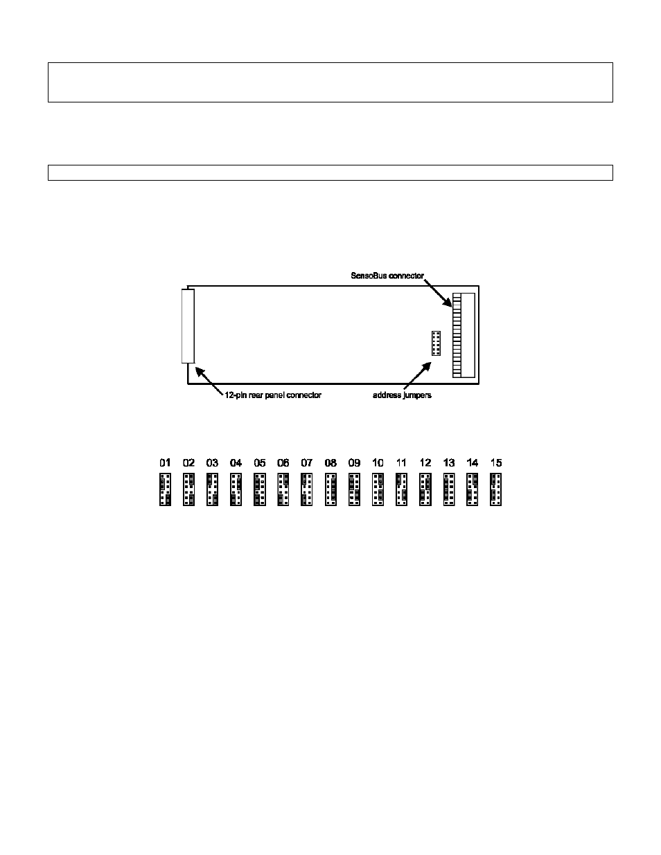
2. Examine the circuit card to be installed and orient it as shown below. On it you will find the address jumper
block.
Figure 6-1: Address Jumper Block Location
3. Change both address jumpers to match the next available channel in the instrument according to the chart
below. Do not skip any channel numbers.
Figure 6-2: Address Jumper Settings
Input Channels, Output Channels and Virtual Channels (such as Mathematics Channels and Split Display
Channels) all require a unique address.
4. Turn the instrument off and remove the power cord from the power source.
5. Find the “Case Removal” in Chapter 4 “Chassis Models” that matches the particular chassis model. Follow the
directions and remove the rear panel.
6. Locate an unused 42-pin SensoBus connector on the SensoBus mother board and make certain that all of its
pins are not bent out of shape. It does not matter into which slot you install the card as the addressing is
implemented with the address jumpers. However, it is most convenient to match the card’s address with the
channel numbers silk-screened on the rear panel.
7. Install the card into an unused 42-pin SensoBus connector on the SensoBus motherboard. Make certain the
card is fully seated.
8. Replace the rear panel.
9. Re-connect the power cord to the power source. Turn the instrument on.
10. Enter the SETUP menu mode, then select “SYSTEM MENU->INSTALL CHANNEL”. The instrument will then
present a menu of card types available for installation.
11. Use the [UP] and [DOWN] buttons to select the card type of the card you wish to install. After you select the
card type to be installed, you are asked “ARE YOU SURE?”. To cancel this operation, select “NO” or press the
[EXIT] button. If “YES” is selected, “WORKING…” is displayed and the installation will commence.