Cooper Instruments & Systems DFI 1650 Multi-Channel Digital Force Indicator User Manual
Page 17
CF 66
11
Rev. C 2/05
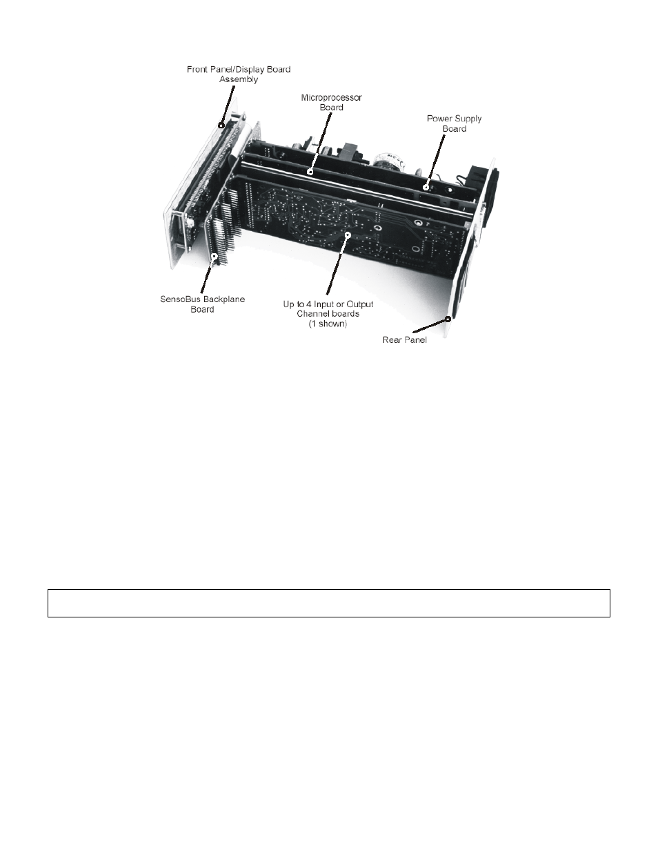
Figure 4-3: Internal Arrangement of DFI 1550 & DFI 1650.
Below is a description of each printed circuit board.
• The SensoBus Backplane Board serves as the connection between all boards in the instrument.
• The Front Panel/Display Board Assembly contains the display and all front panel controls.
• The Power Supply Board contains the +15V, -15V, and +5V power supplies.
• The Microprocessor Board contains the microprocessor, ROM software, storage chip, and the System
connector.
• The Hardware Input/Output Channel Boards plug into the remaining four slots of the SensoBus Backplane
Board.
4.3.9 Cleaning
Turn off the instrument and unplug all connectors. Use a soft cloth or tissue and a mild cleaner. Do not use liquid
or aerosol cleaners. Do not allow any cleaner inside the instrument.
4.3.10 Vehicle Power Option
DFI 1550 and DFI 1650 instruments are available with a vehicle power option for operation with batteries and linear
DC power supplies. See “Specifications” voltage and power requirements.
Due to the momentary startup inrush current of the instrument’s power supply, the use of switching power supplies
with the DFI is not recommended.
4.3.11 Fuse Replacement
The power-line fuses of AC-powered instruments are located within the instrument’s power entry module on the
rear panel. Use two 2A, 250V fast-blow fuses.
4.4 DFI 1650 PT
4.4.1 Differences
DFI 1650PT is the DFI 1650 housed in a portable case.
4.4.2 External Arrangement
The external arrangement of the AC powered DFI 1650PT is given below.