Cooper Instruments & Systems DFI 1650 Multi-Channel Digital Force Indicator User Manual
Page 16
CF 66
10
Rev. C 2/05
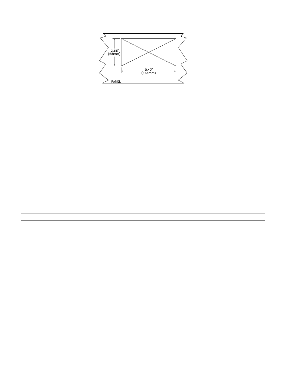
Figure 4-2: Panel Cutout Drawing for DFI 1550 & DFI 1650 (not to scale)
• In the panel or rack, cut a hole as shown above. The panel may be up to ¼” in thickness.
• Use a 0.062” Allen wrench to remove two setscrews that hold the Panel-Mounting Jacks to the case. To do
this, insert the wrench into the side slots at the rear Remove the screws completely.
• Remove the Panel-Mounting Jacks by sliding them toward the rear. If the jacks don’t slide easily, tap them
gently.
• Put the instrument through the hole in the panel.
• Reinsert the Panel-Mounting Jacks into the slide slots. Slide them as far toward the panel as possible.
• Reinsert the setscrews and tighten them. This will force the Panel-Mounting Jacks toward the rear side of the
panel, drawing the instrument tightly into place.
4.3.5 Rack Mounting
A Rack Mounting Kit is available for mounting a single DFI 1550 or DFI 1650 into a 19”, 2U rack. It includes the
Panel-Mounting Jacks described above as well as the 19” rack panel.
4.3.6 Bench Mounting
If bench mounting the instrument, you may want the optional carrying handle/bench stand.
4.3.7 Case Removal
Be sure to remove the power cord from the power source before attempting to remove the instrument from its case.
Use a #0 Phillips screwdriver on the black screws to avoid damaging them.
The rear panel must be removed in order to install or remove channels.
Removal of Rear Panel
Step 1: Remove the four black Phillips-head machine screws that secure the back panel of the instrument to the
case. These screws are located on the rear of the case, one at each of the four corners.
Step 2: Remove the cable shield connection screw to allow the installation or removal of channels per “Input or
Output Channel Installation Procedure”.
Removal of case from entire circuit board assembly
Step 1: Remove the two Phillips-head screws that secure the front panel
Step 2: Remove the front panel and disconnect its two connecting cables.
Step 3: Remove the four black Phillips-head machine screws that secure the back panel of the instrument to the
case. These screws are located on the rear of the case, one at each of the four corners. Do not remove the cable
shields connection screw in the center.
Step 4: The circuit boards will slide out of the rear of the case as a unit.
4.3.8 Internal Arrangement
The figure below shows the names and locations of the printed circuit boards