2 external arrangement, 3 rear panel, 4 panel mounting – Cooper Instruments & Systems DFI 1650 Multi-Channel Digital Force Indicator User Manual
Page 15
CF 66
9
Rev. C 2/05
Operating Temp.
5°C to 40°C
5°C to 40°C
5°C to 40°C
5°C to 40°C
Relative Humidity
80% max. for temperatures up to 30°C; decreasing linearly to 50% max. at 40°C
Other
Indoor use at altitudes up to 2000 m; Pollution Degree 2; Overvoltage Category II
SPECIAL FEATURES
Limits Quantity
N/A
4 std., 16 max.
4 std., 12 max.
4 std., 16 max.
Digital, isolated control inputs
N/A
4
4
4
POWER
Standard AC powered
(automatic selection)
100 to 230 VAC,
47 to 63Hz
100 to 230 VAC,
47 to 63Hz
100 to 230 VAC,
47 to 630Hz
100 to 230 VAC,
47 to 63Hz
Optional Vehicle Powered
11-28 VDC, 20W
11-28 VDC, 20W
11-28 VDC, 20W
N/A
Total Excitation Drive
120 mA max.
120 mA max.
120 mA max.
400 mA max.
4.3 DFI 1550 and DFI 1650
4.3.1 Differences
Model 1550 instruments do not include peak/valley capture or limits features. All other DFI instruments include
peak/valley capture and 4 limit (“alarm”) outputs.
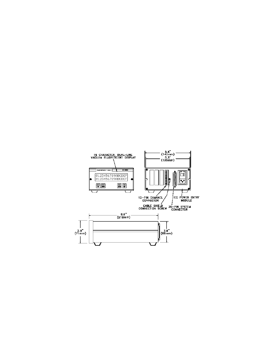
4.3.2 External Arrangement
The external arrangement of the AC powered DFI 1550 and DFI 1650 is given below.
Figure 4-1: External Arrangement of AC powered DFI 1550 and DFI 1650.
4.3.3 Rear Panel
The pinout for the 25-pin System connector is provided later in this chapter. The pinouts for the individual channels
are located in the chapter for that channel.
4.3.4 Panel Mounting
The panel cutout size conforms to the 3/8 DIN standard. Panel-Mounting Jacks are available that slide into two
slots at the sides of the instrument. Use the following procedure to mount a DFI 1550 or DFI 1650 into a panel.