Cooper Instruments & Systems DFI 1650 Multi-Channel Digital Force Indicator User Manual
Page 18
CF 66
12
Rev. C 2/05
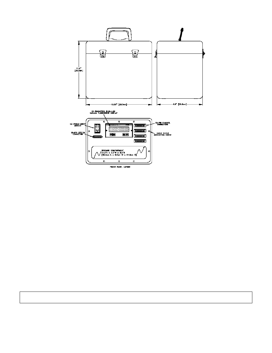
Figure 4-4: External Arrangement of AC powered DFI 1650PT.
4.4.3 Front Panel
The pinout for the 25-pin System connector is provided later in this chapter. The pinouts for the individual channels
are located in the chapter for that channel.
4.4.4 Case Removal
Be sure to remove the power cord from the power source before attempting to remove the instrument from its case.
Step1: Remove the 10 Phillips-head machine screws that secure the front panel to the case.
Step 2: Pull the front panel assembly out of the case.
Step 3: Proceed with DFI 1650 “Case Removal”, see Section 4.3.7
4.4.5 Internal Arrangement
See the DFI 1650 “Internal Arrangement”
4.4.6 Cleaning
Turn off the instrument and unplug all connectors. Use a soft cloth or tissue and a mild cleaner. Do not use liquid
or aerosol cleaners. Do not allow any cleaner inside the instrument.
4.4.7 Vehicle Power Option
The DFI 1650PT is available with a vehicle power option for operation with batteries and linear DC power supplies.
See “Specifications” voltage and power requirements.
Due to the momentary startup inrush current of the instrument’s power supply, the use of switching power supplies
with the DFI is not recommended.
4.4.8 Fuse Replacement
The power-line fuses of AC-powered instruments are located within the instrument’s power entry module on the
rear panel. Use two 2A, 250V fast-blow fuses.