8 spot cutter setup, 9 power “on’ startup sequence – Bio-Rad Components for Older Model Spot Cutter User Manual
Page 11
2.8 Spot Cutter Setup
•
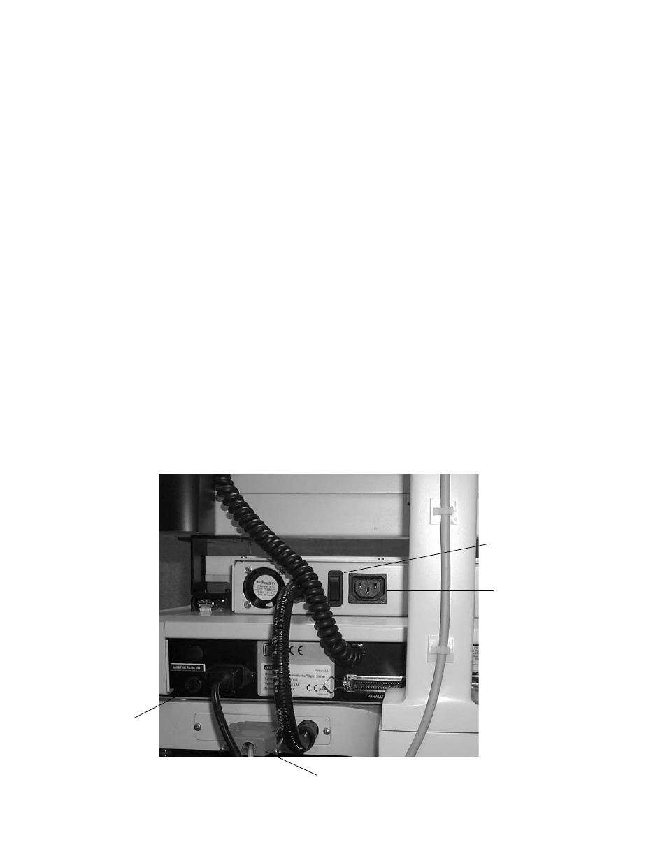
Connect the PC cable. Connect the 9-pin connector to the Com 1 serial port of the
computer and the 25 pin connector to the system communications interface located in
the back panel of the Spot Cutter.
•
Connect the AC power cord to the Spot Cutter instrument.
•
Connect the camera power and communications cable to the PCI interface port on the
PC and the connector on the camera top. Secure the cable through the clips on the back
of the camera arm.
2.9 Power “ON’ Startup Sequence
It is important for the correct sequence of devices to be powered on. The computer must
be turned on and fully booted up before the spot cutter is turned on. If the spot cutter is on first,
or if the computer is re-booted while the spot cutter is on, several commands will not be
communicated. The symptoms are: lights not turning on, and cutting tip not spinning with cut.
When powering up the spot cutter system (including computer) use the following
sequence:
1. Turn on the computer and let it boot up fully to its operating system.
2. Do not open PDQuest yet.
3. Turn on the spot cutter (switch the front black I/O switch to I) and push the yellow
"Start/Pause" button. Let the spot cutter run through its home position routine until it
returns to the back right position (park position).
4. Turn on the camera with the black rocker switch on top of the camera. The green light on
the top indicates the power is on.
5. Open PDQuest and go to either Basic Excision Tool, or Excision Gel Selection.
Fig. 5. Rear panel connections.
8
Light toggle switch
Socket for UV light plug
25 pin serial connection
Mains power connection