B&G H2000 Pilot *DISCONTINUED* User Manual
Page 115
HB-0844-04
4-19
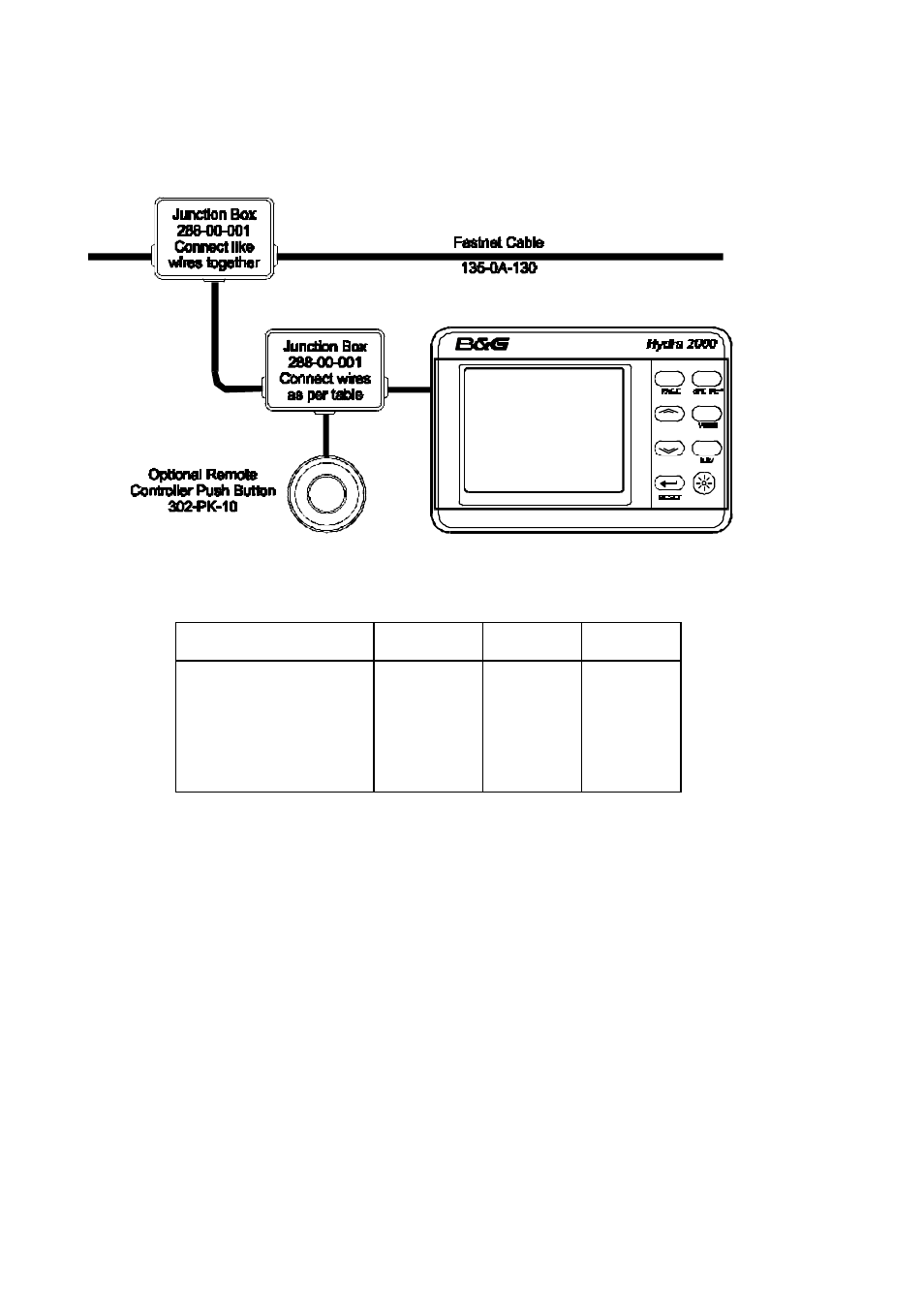
8-BUTTON FULL FUNCTION
DISPLAY WIRING DETAILS
FFD CABLE
FUNCTION
FFD CABLE
COLOUR
SYSTEM
NETWORK
REMOTE
BUTTON
Network Data -ve
Green
Green
Network Data +ve
White
White
Network Cable Shield
Shield
Shield
Ground
Black
Black
Blue
Supply +ve
Red
Red
Remote Control Button
Yellow
Red
Not used
Brown
INSTALLATION NOTES FOR HYDRA 2000
•
The system requires at least one FFD.
•
An FFD can be connected at any point on the system network.
•
Multiple FFD's can be used on the system network. Each can control and enter data into the system
processor memory.
•
FFD's can be used in combination with all other display types; that is NMEA FFD's, Halcyon displays,
20/20 and Pilot displays.
SCREENED CABLES
•
Shielded cables are supplied to provide protection against unwanted emissions (EMC) and must be
connected in accordance with these instructions.
NETWORK TERMINATION
•
If the FFD is the last unit on the system network a network terminator MUST be fitted across the network
data wires, that is between the green and white wires.