Pfc1600 plumbing, Figure 24, Refer to figure 24 – Great Plains PFC2000 Operator Manual User Manual
Page 51
Appendix 49
03/28/2007
407-158M
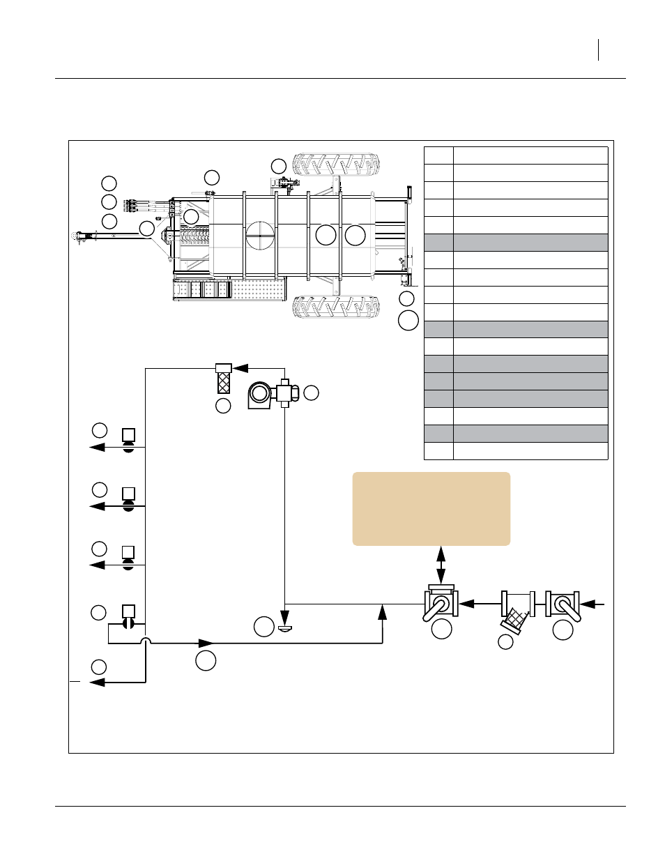
PFC1600 Plumbing
This figure shows the general location and a flow/control diagram of the plumbing system.
4
1
2
3
3
2in
2in
2in
4
in
1600
Figure 24
PFC1600 Plumbing
26082
Manifold valve #1 (planter L.)
Manifold valve #2 (planter C.)
Manifold valve #3 (planter R.)
Recirculation valve
Gauge line
Ground drive pump
Quick-fill strainer
Pump strainer
Quick-fill shut-off valve
1600 gal discharge line valve
recirculation to 1600 gal tank
1600 gal drain cap
26082
This manual is related to the following products:
See also other documents in the category Great Plains Gardening equipment:
- 1200 Parts Manual (210 pages)
- 706NT Material Rate (46 pages)
- 706NT Material Rate (50 pages)
- 2N-2410 Operator Manual (48 pages)
- 2N-2410 Operator Manual (56 pages)
- 12 Series Drills Assembly Instructions (6 pages)
- X-PresS 2006 Assembly Instructions (50 pages)
- TM500 Operator Manual (62 pages)
- 2010HDP Operator Manual (166 pages)
- YP1630F Material Rate (42 pages)
- YP2425 Operator Manual (162 pages)
- 3S-5000 Operator Manual (94 pages)
- 3PYP Operator Manual (188 pages)
- 3N-3010P Assembly Instructions (2 pages)
- 3N-3010 Assembly Instructions (9 pages)
- 3N-3010P Assembly Instructions (9 pages)
- PFH-15 Predelivery Manual (23 pages)
- PFH-15 Operator Manual (46 pages)
- PFH-15 Operator Manual (26 pages)
- P15126 Serial No 12724 (34 pages)
- DVN 8321 Operator Manual (38 pages)
- 3P500 Assembly Instructions (22 pages)
- 3P600 Assembly Instructions (12 pages)
- 605NT Assembly Instructions (8 pages)
- 605NT Assembly Instructions (4 pages)
- CPH-12 Assembly Instructions (3 pages)
- YP1625A-2420 24 Row 20-Inch Quick Start (6 pages)
- 8323 FCF Predelivery Manual (124 pages)
- P13937 (20 pages)
- 3323 DH Parts Manual (114 pages)
- YP3025-1820 25 Series 18 Row 20 Inch Quick Start (5 pages)
- CF500 Operator Manual (38 pages)
- PFH-15 Assembly Instructions (30 pages)
- 3500TM Parts Manual (106 pages)
- 1800TM Parts Manual (158 pages)
- YP2425A-2470 24 Row 70 cm Quick Start (5 pages)
- Simba Culti Press Operator Manual (38 pages)
- RU1999 Parts Manual (58 pages)
- 3N-30P Assembly Instructions (10 pages)
- 2510HDP Operator Manual (180 pages)
- YP1220 Parts Manual (136 pages)
- 3P500 Material Rate (68 pages)
- YP2425-3620 36 Row 20 Inch Quick Start (5 pages)
- 706NT Operator Manual (53 pages)
- 706NT Operator Manual (22 pages)