Standard function with switches – SARGENT MPower 4000 User Manual
Page 6
80-9369-0901-021 (12-02 )
6
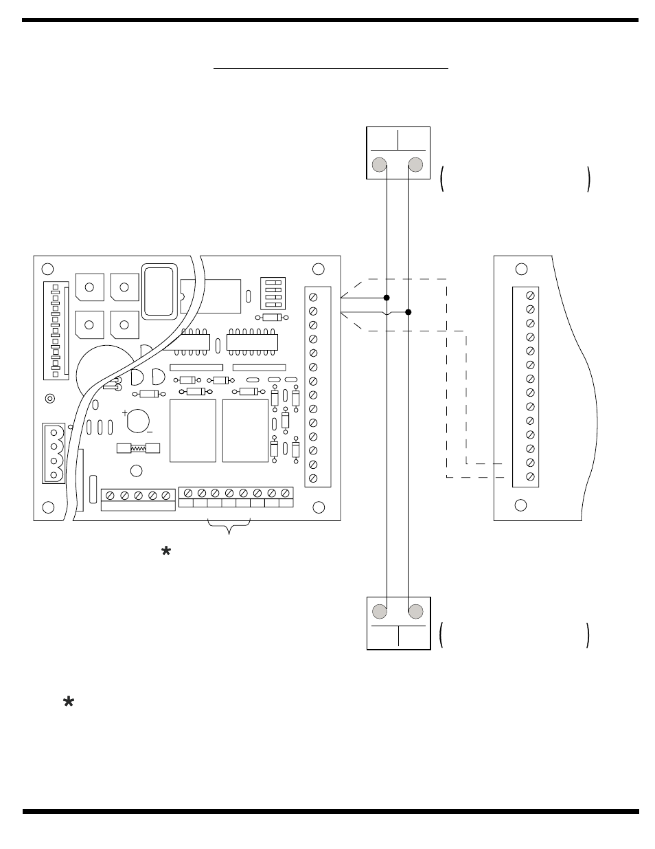
Standard Function with Switches
Note 3:
If product being connected does
not have an integrated diode, one
must be installed across contracts
to protect relays . Suggested diode is
1N4001 or equivalent.
See pages 9 - 11 for illustration of use.
Notes:
1. Power input Door Operator Unit is at
Power Input Terminal Strip (not shown)
120VAC 60Hz.
2. Current draw must not exceed 0.500
amps at terminal JP4 – 2.
5
678
90
1
23
4
5
678
90
1
23
4
5
678
90
1
23
4
5
678
90
1
23
4
JP3
JP2
CL/AS DLY VEST DLY
EXSOL DLY
M. DLY
G
EM
G
H+
V
L
2
G
L1
MO
T
OR/SOLENOID
JP4
JP1
JP5
OFF
ON
SW1
P/A
A/D
RES1
RES2
0/0
RES1
A
UX2
GND
INV
OUTV
GND
R
F
T
GND
A
UX2
GND
PDET
GND
A
UX1
GND +24V NO1 CO1 NC1 NO2 CO2 NC2
NEU HOT GND
18VAC
1 2 3 4 5 6 7 8
14
13
12
11
10
9
8
7
6
5
4
3
2
1
JP1
0/0
RES1
A
UX2
GND
INV
OUTV
GND
RFT
GND
A
UX2
GND
PDET
GND
A
UX1
1
2
3
4
5
6
7
8
9
10
11
12
13
14
RELAY CONTACTS FOR
ELECTRIC STRIKE.
ELECTRIC LATCH RETRACT
EXIT DEVICE, MAGNETIC
LOCK, ETC.
See Note 3.
Wall Switch, Card
Reader, Key Switch,
etc.
Normally Open Momentary
dry contacts
Wall Switch, Card
Reader, Key Switch,
etc.
Normally Open Momentary
dry contacts
Door 1
Door 2
Operation:
Doors are normally closed.
Activating either switch will open both doors. Door will
close after hold open time delay has elapsed.