Electric latch retraction exit device wiring, Latch retraction exit device – SARGENT MPower 4000 User Manual
Page 13
80-9369-0901-021 (12-02 )
13
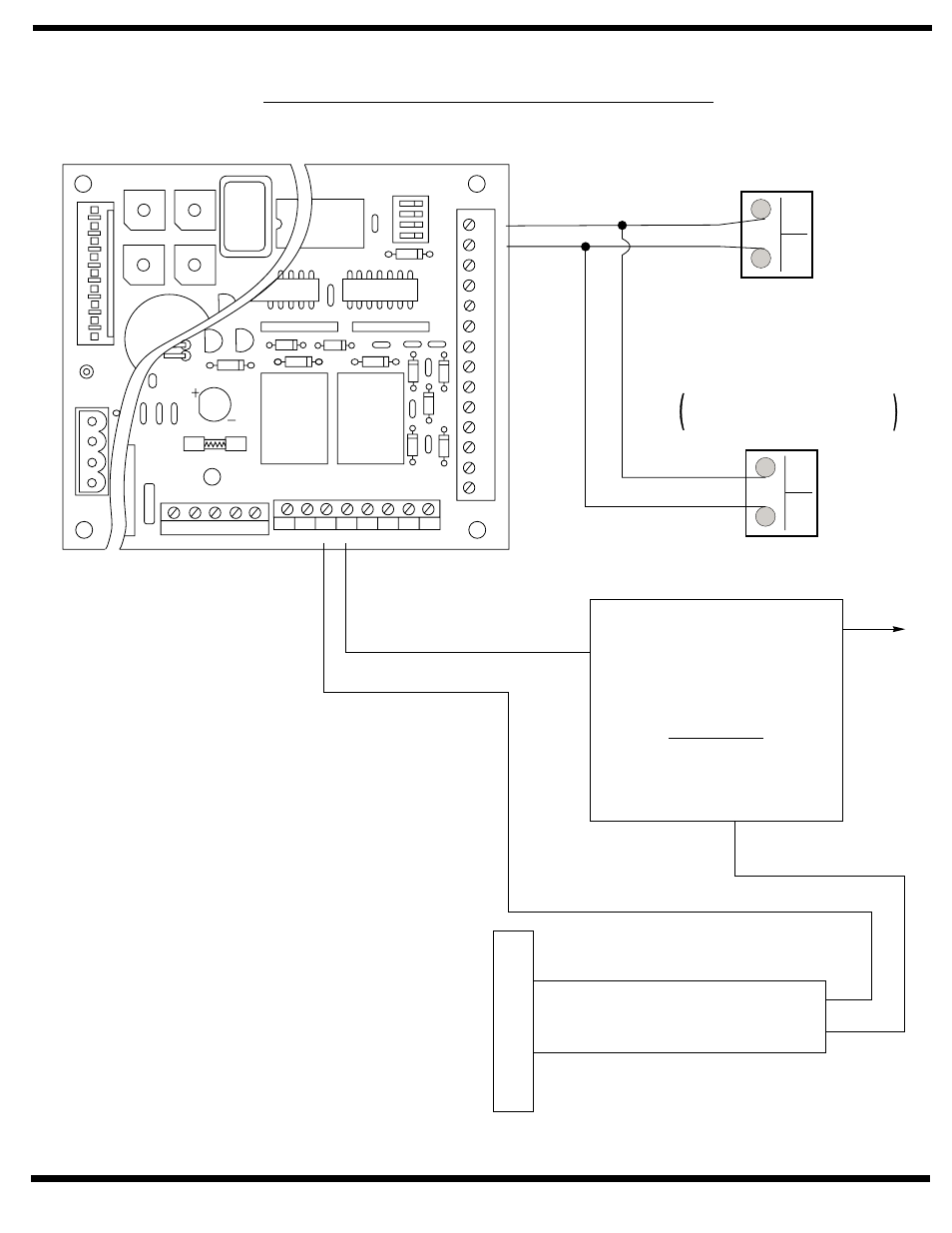
Electric Latch Retraction Exit Device Wiring
Notes:
1. Power input Door Operator Unit is at Power Input
Terminal Strip (not shown) 120VAC 60Hz.
2. Refer to Manufactures wiring instructions for Latch
Retraction Devices not shown.
3. Power Supply must be .900 Amps minimum per 56-
Latch Retraction Exit Device.
4. Set switch SW2 to position 3 for 1 second delay.
56-
Latch Retraction Exit Device
Operation:
Door is normally closed and latched.
Activating the switch will retract the exit device then the
operator will open the door.
The door will close after the hold open time delay has
elapsed.
Exit device allows egress at all times. Exit device allows
egress during power failure.
5
678
90
1
23
4
5
678
90
1
23
4
5
678
90
1
23
4
5
678
90
1
23
4
JP3
JP2
CL/AS DLY VEST DLY
EXSOL DLY
M. DLY
G
EM
G
H+
V
L
2
G
L1
MO
T
O
R/SOLENOID
JP4
JP1
JP5
OFF
ON
SW1
P/A
A/D
RES1
RES2
0/0
RES1
A
UX2
GND
INV
OUTV
GND
R
F
T
GND
A
UX2
GND
PDET
GND
A
UX1
GND +24V NO1 CO1 NC1 NO2 CO2 NC2
NEU HOT GND
18VAC
1 2 3 4 5 6 7 8
14
13
12
11
10
9
8
7
6
5
4
3
2
1
Wall Switch, Card
Reader, Key Switch,
etc.
Normally Open Momentary
dry contacts
(+)
(-)
120 VAC
24VDC
Filtered and Regulated
Power Supply
*See Note 3
+24VDC
-24VDC
RED
BLACK