Electric dogging exit device wiring – SARGENT MPower 4000 User Manual
Page 12
80-9369-0901-021 (12-02 )
12
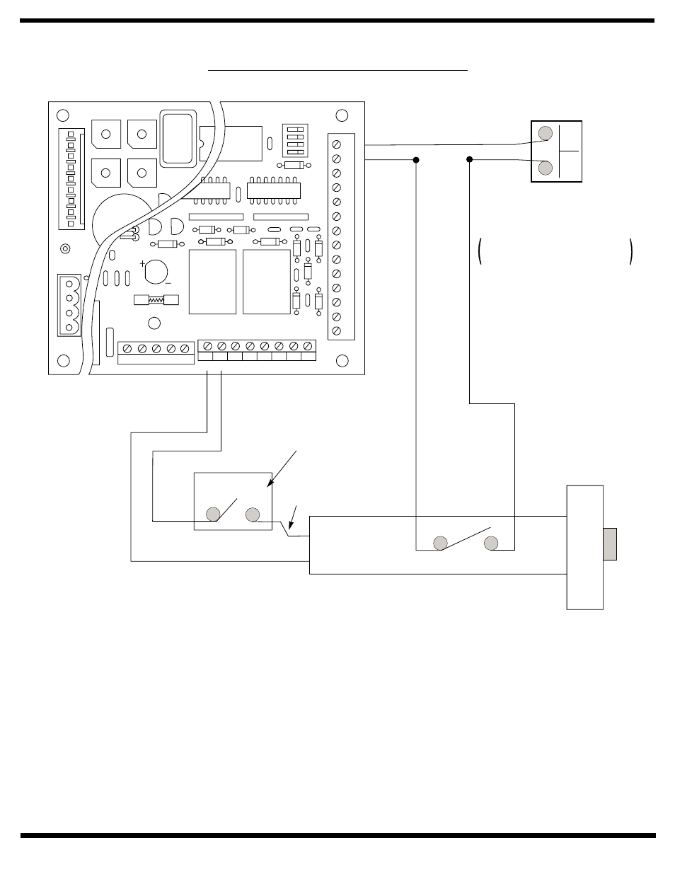
Notes:
1. Power input Door Operator Unit is at
Power Input Terminal Strip (not shown)
120VAC 60Hz.
2. Current draw must not exceed 0.500
amps at terminal JP4 – 2.
Operation:
Door is normally closed and latched, with wall switch
disabled.
Turning key switch ON will apply power to the exit device.
The first depression on the device touchpad will
electrically dog the device for push / pull operation.
The door will now open automatically when the wall
switch is depressed.
The device will relatch during a power failure or when the
keyswitch is turned off.
The exit device allows egress at all times. The exit device
allows egress during power failures.
Electric Dogging Exit Device Wiring
5
678
90
1
23
4
5
678
90
1
23
4
5
678
90
1
23
4
5
678
90
1
23
4
JP3
JP2
CL/AS DLY VEST DLY
EXSOL DLY
M. DLY
G
EM
G
H+
V
L
2
G
L1
MO
T
OR/SOLENOID
JP4
JP1
JP5
OFF
ON
SW1
P/A
A/D
RES1
RES2
0/0
RES1
A
UX2
GND
INV
OUTV
GND
R
F
T
GND
A
UX2
GND
PDET
GND
A
UX1
GND +24V NO1 CO1 NC1 NO2 CO2 NC2
NEU HOT GND
18VAC
1 2 3 4 5 6 7 8
14
13
12
11
10
9
8
7
6
5
4
3
2
1
Touch Bar Monitor Switch
ON / OFF
Key Switch
24 VDC Electric Dogging Exit
Device w/ Touch Bar Monitoring
(55-58-80 Series Exit Device)
Wall Switch, Card
Reader, Key Switch,
etc.
Normally Open Momentary
dry contacts
RED
BLACK
(+)
(-)