SARGENT MPower 4000 User Manual
Page 5
80-9369-0901-021 (12-02 )
5
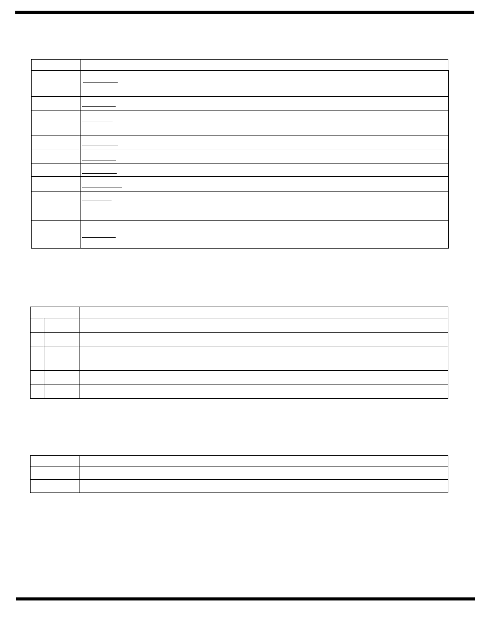
TERMINAL
D E S C R I P T I O N
1
NEU
Common 120V connection to Input Power Terminal 22.
2
HOT
Hot 120V connection to Input Power Terminal 24.
3
GND
Ground connection secured to backplate under head of (green) ground screw that is located under Main PC Board.
Screw Labeled “GND”
4
18VAC
From secondary of 120V / 24V transformer.
5
18VAC
From secondary of 120V / 24V transformer.
JP5 Terminal Strip – Factory Wired Connections.
TERMINAL
D E S C R I P T I O N
MOTOR
Motor Connection.
SOLENOID
Solenoid coil connection.
JP3 Terminal Strip – Factory Wired Connections.
JP2 Terminal Strip – Factory Wired Connections.
G
– Ground. Common connection for L1 and L2 inputs.
Black Wire
L2
– High side of L2 Input signal for ELS Board. Detects the Fully Open Position stored in the ELS Board
during the teaching mode.
Blue Wire
+V
+24VDC. This terminal is used to supply power to the ELS Board.
Yellow Wire
H
– Hold Open contact of “OFF” “ON” “H/O” switch assembly.
Violet Wire
G
– Ground. Common contact of “OFF” “ON” “H/O” switch assembly.
White Wire
M
Orange Wire – ON contact of “OFF” “ON” “H/O” switch assembly.
E
– Emergency Hold Open Release. This contact is used in conjunction with the ELS board to close the
door immediately at any point of door opening once an obstruction on opening is encountered. It is used with
terminal JP2 – G.
Red Wire
G
– Ground. Use with terminal Jp2 – E for Emergency Hold Open Release.
Black Wire
TERMINAL
D E S C R I P T I O N
L1
– High side of L1 Input signal from ELS Board. Detects door motion to open door when door is pushed
or pulled in the open direction. Movement of potentiometer on ELS Board signals L1 input.
White Wire