Terminal description – SARGENT MPower 4000 User Manual
Page 2
80-9369-0901-021 (12-02 )
2
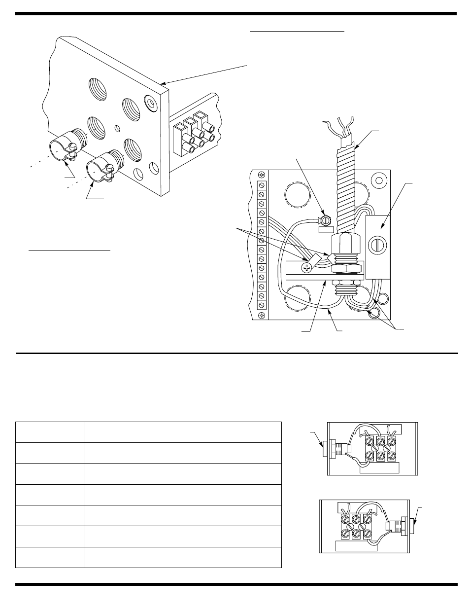
CONCEALED WIRING
Thread conduit fitting(s) into backplate as shown.
A second conduit fitting is required for low voltage
control wiring. CHECK LOCAL CODES. Pull
conduit out of header and attach to conduit
fittings before mounting Operator to door frame.
Attach incoming ground wire to backplate with
ground screw as illustrated below.
SURFACE WIRING
An optional bracket is provided for use with
surface wiring. Remove the two cable clamps
screws and slip the bracket under the cable
clamps. Push the cable clamp screw through
the bracket holes and tighten.
½” conduit
fittings can now be installed on the bracket.
INSTALLER / USER INFORMATION
Input Power Terminal Strip
Earth Ground Wire Connection
– 120VAC, (+10% - 15%) Input Voltage. Maximum wire size 12 AWG at terminals HOT and COM.
Terminals 22 through 25 are factory wired using 18AWG wire.
– Ground wire must be secured to backplate under head of (green) ground screw nearest to “T1” Power
Input Terminal Strip bracket. Screw labeled “GND”.
Terminal
Description
HOT
(Line)
25
23
24
22
COM
(Neutral)
Common power lead
Hot power lead
Fuse connection
Hot connection to PC board JP5 – 2 and to hot
primary side of 120V / 24V transformer.
Fuse connection
Common connection to PC board JP5 – 1 and to
common primary side of 120V / 24 V transformer.
Left Hand Double Lever, Push Side
Right Hand Slide Track, Pull Side
Right Hand Double Lever, Push Side
Left Hand Slide Track, Pull Side
Low Voltage
Control
Wiring
Incoming
Power
(Green) Ground Screw
Conduit by Others
(from top)
“T1” Power
Input
Terminal Strip
Bracket
Cable
Clamps
Optional Bracket
(for surface wiring)
Ground
Lead
Power
Leads
24
HO
T
COM
25
23
22
Fuse F2
*
24
HO
T
COM
25
23
22
Fuse F2
*