SARGENT MPower 4000 User Manual
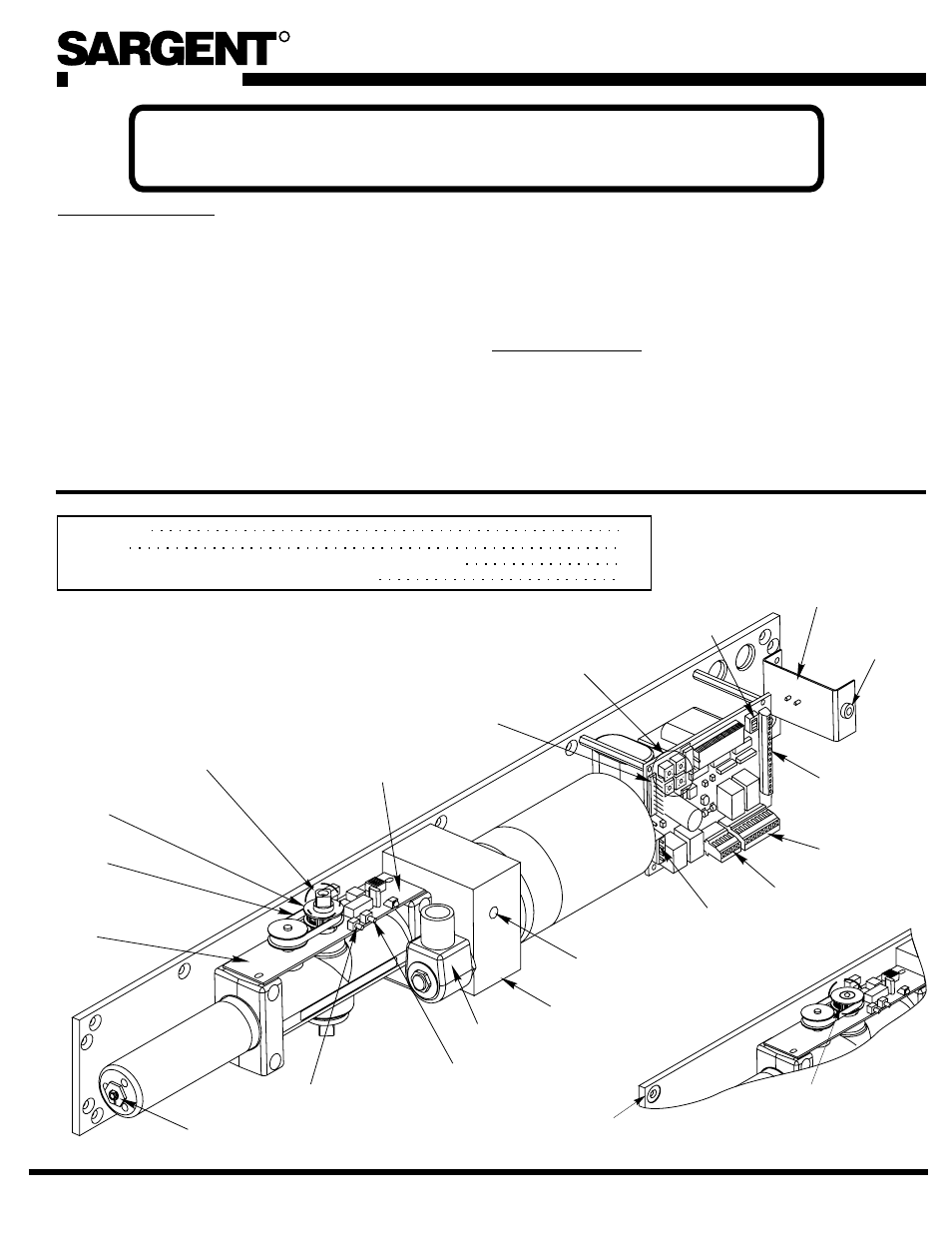
General data, A7666a, Handed unit shown
80-9369-0901-021 (12-02 )
Low Energy Door Operators
Wiring Instructions For 4051, 4052, 4060, 4067
80-9369-0901-021 (12-02 )
120 VOLT POTENTIAL PRESENT. MAKE SURE POWER INPUT TO UNIT IS
TURNED OFF DURING INSTALLATION AND WIRING PROCEDURE.
REQUIREMENTS:
•
•
•
•
U.L. labeled fire or smoke barrier door assemblies require
that the 120VAC, 60Hz power input to the Power Door
Operator
be supplied through normally closed alarm
contacts of the alarm system/alarm panel.
Note:
All wiring and connections use standard wiring practice
conforming with local wiring codes.
Power inputs at terminal strip T1 and at terminal strip JP4 must
be made with copper wire only.
Maximum wire size is:
12 AWG at Power Input Terminal Strips
14 AWG at Terminal Strips JP1 And JP4
No power/voltage inputs are to be made to the Door
Operator unit except 120VAC, 60Hz (+10% -15%) at terminals
HOT and COM of the Power Input Terminal Strip T1.
GENERAL DATA:
•
•
•
Typical field connections for flexible conduit illustrated on page 2.
Power input terminal strip T1 at terminals Hot and COM must be
120VAC at 60Hz (+10% -15%).
Current draw at auxiliary contact JP4 – 2 must not exceed 0.500
amps, for auxiliary devices.
•
•
Maximum current draw of Door Operator units without peripheral
sensors or scanners is 1.5 amps when motor is operating, .050 amps
in standby.
Maximum current draw from auxiliary devices is 0.500 amps
(terminals JP4 – 1 and JP4 – 2).
Fuse “F2” protects the Electronic Control Module and Transformer
circuit and is a 3 amp slow blow fuse.
11/16" Power
Adjustment Nut
JP2
Terminal
Strip
SW1
Dip
Switches
Main Board
Bracket for
Input Power
Terminal Strip
T1
JP1
Terminal
Strip
JP4
Terminal
Strip
JP5
Terminal
Strip
JP3
Terminal
Strip
(SC) Speed
Control Valve
Application
(REF)
Solenoid
Rotary Switches/
Timer Pots
ELS Board w/
ELS Board
Pulley
Spindle Timing
Pulley for Field
Reversible
Units
ELS Board
LED
Door Calibrate
Open Position
Door Calibrate
Close Position
Timing Belt
SC
PUS
H
Fuse
F2
Field Reversible
Unit Shown
Square Spindle End
Protrudes
Spindle Timing
Pulley
Handed Units
Handed Unit
Shown
R
A7666A
Requirements
Unit Wiring
Control Module Layout and (Input/Output Connections; Functions)
Typical Application – Point to Point Wiring Diagrams
1
2
3-5
6-15
1