SARGENT MPower 4000 User Manual
Page 4
80-9369-0901-021 (12-02 )
4
Length of Time
(Seconds)
Settings
0
1
2
3
4
5
6
7
0.0
0.2
0.5
1.0
2.5
1.5
3.5
4.5
Chart 1 – SW2, M DLY
Length of Time
(Seconds)
Settings
0
1
2
3
4
5
6
7
0
1
2
4
8
6
10
12
Chart 2 – SW3, EXSOL DLY
Length of Time
(Seconds)
Settings
0
1
2
3
4
5
6
7
0
1
3
6
14
9
21
30
Chart 3 – SW4, VEST DLY
Length of Time
(Seconds)
Settings
0
1
2
3
4
5
6
7
0
2
5
10
20
15
25
30
Chart 4 – SW5, CL/AS DLY
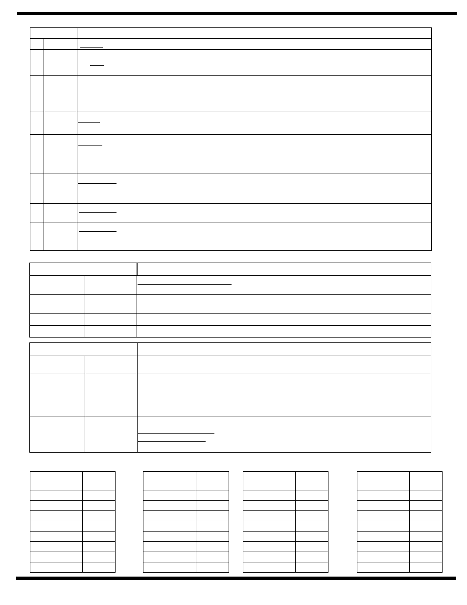
TERMINAL
D E S C R I P T I O N
1
GND
Ground
2
+24
24VDC (unregulated)
to a maximum current draw of 0.500 amps. Use with ground terminal JP4 – 1.
use this supply with 56- Latch Retraction Exit Device.
A separate 24VDC filtered and regulated supply must be used.
output
DO NOT
3
NO1
Control (Relay Contact Only – 5Amp @ 24VDC) – Normally open contact that is switched by Relay K3 (on main
board) to close. Relay K3 will remain switched for a period set by SW – 3 EXSOL DLY rotary switch / timer pot.
Use with terminal JP4 – 4 CO1. Coordinate use of this terminal with delayed start of motor using rotary timer pot
SW – 2 M DLY.
4
CO1
Control (Relay Contact Only
) – Common contact for use with terminals JP4 – 3 NO1 and JP4 - 5
Nc1.
– 5Amp @ 24VDC
5
NC1
Control (Relay Contact Only – 5Amp @ 24VDC) – Normally closed contact that is switched by Relay K3 (on main
board) to open. Relay K3 will remain switched for a period set by SW – 3 EXSOL DLY rotary switch / timer pot.
Use with terminal JP4 – 4 CO1. Coordinate use of this terminal with delayed start of motor using rotary timer pot
SW – 2 M DLY.
6
NO2
Alarm Delay (Switching Contact Only
) – Normally open contact that is switched by relay K4 (on
main board) to close. Relay K4 will remain switched for a period set by Dip Switch SW1 – 2 A/D (OFF = 30 second
delay; ON = 60 second delay). Use with terminal JP4 – 7 Co2.
– 5Amp @ 24VDC
7
CO2
(Switching Contact Only
) – Common contact for use with terminals JP4 – 6 NO2
and JP4 – 8 NC2.
Alarm Delay
– 5Amp @ 24VDC
8
NC2
(Switching Contact Only – 5Amp @ 24VDC) – Normally closed contact that is switched by relay K4 (on
main board) to open. Relay K4 will remain switched for a period set by Dip Switch SW1 – 2 A/D (OFF = 30 second
delay; ON = 60 second delay). Use with terminal JP4 – 7 Co2.
Alarm Delay
JP4 Terminal Strip – Maximum wire size 14AWG.
DIP SWITCHES (MAIN BOARD)
DESCRIPTION
1
P/A
Door Operator Function Switch – OFF position selects the Power Operator Function. On
position sets the Power Assist Function.
2
A/D
Alarm System Delay Timer – This switch is used in conjunction with terminal Jp1– 1, 0/0 for
optional function 2. (OFF = 30 second delay, ON = 60 second delay).
3
RES1
DIAGNOSTIC USE. FOR FACTORY AUTHORIZED PERSONAL.
4
RES2
DIAGNOSTIC USE. FOR FACTORY AUTHORIZED PERSONAL.
ROTARY SWITCHES
DESCRIPTION
SW2
M DLY
This rotary switch or timer pot sets the length of delay for motor start up to allow for “unlocking”
of exit devices, electric strikes, magnetic locks, etc. See Chart 1 for delay times.
SW3
EXSOL DLY
This rotary switch or timer pot sets the length of time that a solenoid remains either energized or
de-energized to allow “unlocking”. Used in conjunction with terminals JP4 – 3, JP4 – 4, JP5 – 5.
See Chart 2 for length of time.
SW4
VEST DLY
This switch or timer pot sets the length of time between receipt of the “In Vestibule” signal
(terminal JP1 – 5) and motor start-up. See Chart 3 for delay times.
SW5
CL/AS DLY
Controls either one of two function times:
– Sets length of time door holds open at fully “taught” open position.
– Sets length of time motor and pump will operate to reduce opening
force. When time elapses, the door force reverts to full opening spring force set.
Power Operator Function
Power Assist Function
Main Board Switches