Profile series v.g1.5 cylindrical lock, Lock preset to, 5–lock installation – SARGENT Profile Series v.G1.5 Cylindrical Locks User Manual
Page 8
6
800-810-WIRE (9473) • www.sargentlock.com • A7854B
Profile Series v.G1.5 Cylindrical Lock
05/06/09
A7854:B
Copyright
©
2009,
Sargen
t
Manufacturing
Company
,an
A
S
S
A
AB
LO
Y
G
roup
company
.All
right
s
reser
ved
.
Reproduction
in
whole
or
in
par
t
without
the
express
writ
ten
permission
of
S
AR
G
EN
T
Manufacturing
is
prohibited
.
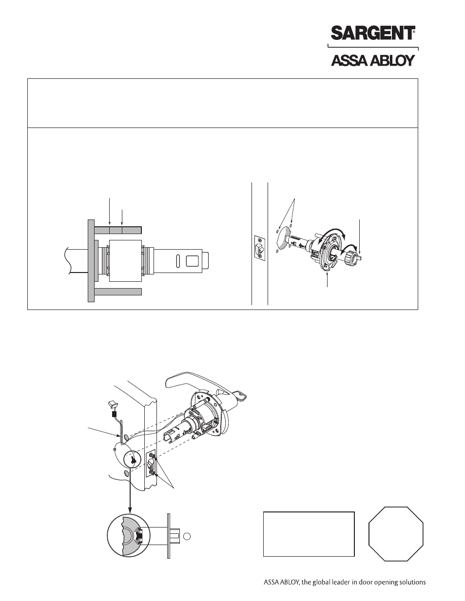
Lock Preset to:
• Through-bolt location– 12 & 6 o'clock
• Door thickness– 1-3/4" thick- see below for other door conditions
Adjustment for different through-bolt and door thickness:
• Through-bolt location– rotate outside rose to match door
• Door thickness– rotate outside rose to align door thickness marking with lockbody edge
• Spacer bushing– remove and realign to fit into back of lever
For wood
door only
Screws partially
tightened
6.5–Lock Installation
IMPORTANT:
Door must remain open
during installation.
Use door stop.
IMPORTANT
Lockbody
must be
centered
in the door
3
1-3/4" thick door
2" thick door
Through-bolt
holes
Rotate to match
through-bolt holes in door
Spacer bushing
1. Feed wires into the lock body hole, from outside of door.
2. Lock body into cross-bore hole from outside of the door (locked side).
3. Lock body must engage both the latch unit prongs and tail piece, as shown.