Profile series v.g1.5 cylindrical lock, Operational check, Installation of rf technology lock – SARGENT Profile Series v.G1.5 Cylindrical Locks User Manual
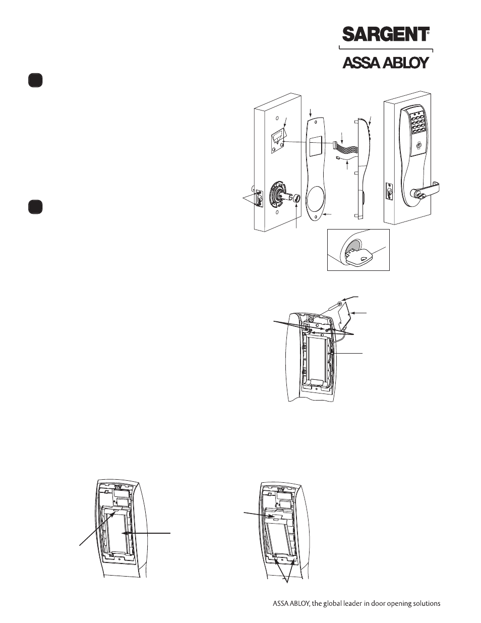
Page 16: 1–installation of the top through-bolt screw, 2–removal procedure for the battery keeper
14
800-810-WIRE (9473) • www.sargentlock.com • A7854B
Profile Series v.G1.5 Cylindrical Lock
05/06/09
A7854:B
Copyright
©
2009,
Sargen
t
Manufacturing
Company
,an
A
S
S
A
AB
LO
Y
G
roup
company
.All
right
s
reser
ved
.
Reproduction
in
whole
or
in
par
t
without
the
express
writ
ten
permission
of
S
AR
G
EN
T
Manufacturing
is
prohibited
.
Operational Check
7
Installation of RF Technology Lock
8
For devices with cylinders:
1. Insert key into cylinder and rotate.
2. The key will retract the latch. Key should rotate freely
3. Inside lever retracts latch and deadbolt (if provided)
4. Enter 1234* to unlock outside lever handle and retract
latch and deadbolt (if provided)
5. If lock is prox only (G1-PA) or RF Technology with
Prox (G1-TA) - refer to Keypad programming
instruction manual
The RF Technology Lock (G1-TU, G1-TA, G1-TP) is installed
as described in section 6 with the following exceptions:
• Installation of the top through-bolt screw
• Removal process for the battery keeper
The antenna board must be carefully moved to access the
upper through-bolt screw. Care should be taken to prevent
damage to the antenna retaining tabs during this process.
Press the two tabs away from the antenna board and lift the
board off the mounting posts. Insert the flat head through-
bolt and secure the escutcheon in place. After tightening the
top through-bolt, replace the antenna board by placing it on
the mounting posts and pressing into the retaining tabs.
8.1–Installation of the top through-bolt screw
To remove the battery keeper, a flat bladed screwdriver or similar tool must be used.
Insert the screwdriver into the slot at the top of the battery keeper, lift up and pull the top of the keeper away from
the batteries.
To install, insert the tabs on the bottom of the keeper into the battery compartment slots and press the keeper
tightly against batteries.
8.2–Removal procedure for the Battery Keeper
Flathead through-bolt
Antenna
Board
Retaining
Tabs
Mounting
Posts
Controller
Assembly
Insert screwdriver tip
and lift up
Battery
keeper
Tip out
Keeper tabs
Outside of
door
Ground
wire
8-32 Flat head
s
Weather
Seal
Gasket
Latch
screws
Cylinder
spacer
Ribbon
cable with
connector
Outside
Escutcheon
Fire stop
plate
Weather
seal gasket