Profile series v.g1.5 cylindrical lock, 3–frame preparation for strike, 4–latchbolt and fire stop plate installation – SARGENT Profile Series v.G1.5 Cylindrical Locks User Manual
Page 7: Inside of door
5
A7854B • 800-810-WIRE (9473) • www.sargentlock.com
Profile Series v.G1.5 Cylindrical Lock
05/06/09
A7854:B
Copyright
©
2009,
Sargen
t
Manufacturing
Company
,an
A
S
S
A
AB
LO
Y
G
roup
company
.All
right
s
reser
ved
.
Reproduction
in
whole
or
in
par
t
without
the
express
writ
ten
permission
of
S
AR
G
EN
T
Manufacturing
is
prohibited
.
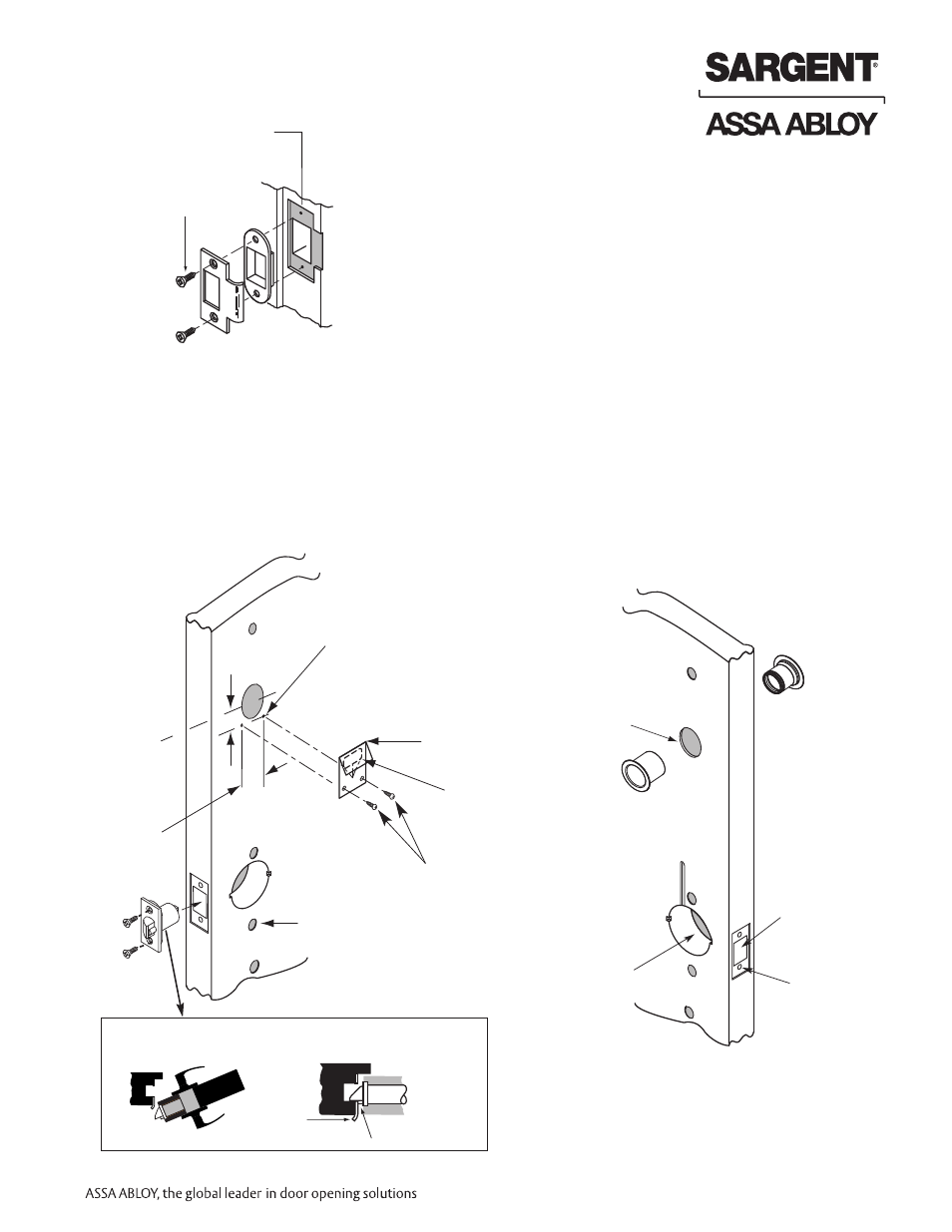
6.3–Frame Preparation for Strike
Non Fire Rated Exterior Doors–
Install Weather Conduit (P/N 52-2847)
as shown below
6.4–Latchbolt and Fire Stop Plate Installation
1. Install latch with beveled bolt facing the strike.
2. Attach with two screws but
DO NOT tighten completely at this time.
3. Attach Fire Stop Plate with two screws.
Note: Required for all Fire Rated doors
IMPORTANT: Latch bevel must match door bevel and
deadlocking latch must stop on strike when door is closed
Fire Rated Doors– Install Fire
Stop Plate (P/N 52-0033)
as shown below
Strike
Screws (2)
#8-32 x 3/4"
Centerline of
latch front and
strike
1-1/2"
(2) 1/8" Dia. holes
required
7/8"
Fire
stop plate
Through-bolt
hole (2)
(2) Self tapping
screws #8 x 1/2"
for wood &
metal doors
Slot
CL of
1-1/2" Dia.
Lockbody
hole
Latchbolt
door prep
Pre-drill
and/or tap
holes (2)
Inside
of door
Hole for ribbon
cable from keypad
to controller
Note: Once
Weather Conduit
is assembled, it
can be difficult
to take apart