Carrier FLOTRONIC II 30GN040-420 User Manual
Page 69
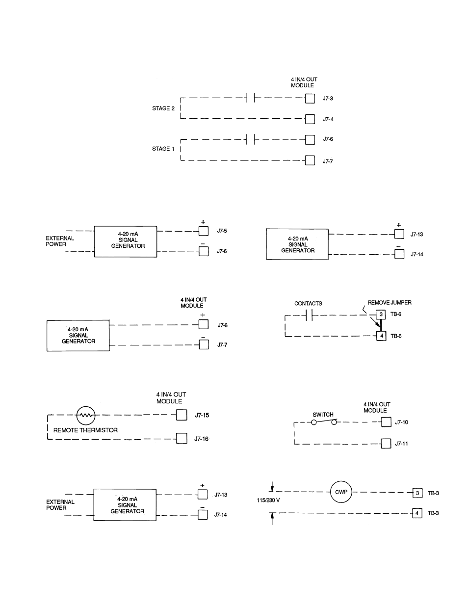
FIELD WIRING
Refer to Fig. 25-35 for field wiring.
NOTE: Contacts must be rated for dry circuit application, capable of
reliably switching a 5 vdc, 1 mA to 20 mA load.
Fig. 25 — Demand Limit — Two External
Switch Inputs
Fig. 26 − Demand Limit — 4-20 mA Signal
(Externally Powered)
Fig. 27 — Demand Limit — 4-20 mA Signal
(Internally Powered)
Fig. 28 — Remote Reset from Space or
Outdoor-Air Temperature
Fig. 29 — Remote Reset from 4-20 mA Signal
(Externally Powered)
Fig. 30 — Remote Reset from 4-20 mA Signal
(Internally Powered)
TB — Terminal Block
NOTE: Contacts must be rated for dry circuit application, capable of
reliably switching a 5 vdc, 1 mA to 20 mA load.
Fig. 31 — Remote On/Off
Fig. 32 — Remote Dual Set Point Control
CWP — Chilled Water (Fluid) Pump
TB
— Terminal Block
Fig. 33 — Chilled Fluid Pump
69