Carrier FLOTRONIC II 30GN040-420 User Manual
Page 52
The voltage supplied to the processor is polarized. When
checking for proper voltage supply, be sure to consider this
polarity. If voltage appears to be within acceptable toler-
ance, check to be sure the transformer supplying PS1 is not
grounded. Grounding the supply transformer can result in
serious damage to the control system.
Code 29
LOCAL/ENABLE-STOP-CCN Switch Failure
(switch resistances out of range) (alarm)
This fault occurs due to the failure of the switch or due to
a wiring error.
Code 30
Reset input failure (4 to 20 mA) (alert)
Code 31
Demand limit input failure (4 to 20 mA) (alert)
These codes apply only if unit is configured for these func-
tions. If 4 to 20 mA signal is less than 4 or more than
20 mA, reset or demand limit function is disabled and unit
functions normally. If mA signal returns to the acceptable
range, function is automatically enabled.
Code 32
Loss of communication with compressor
relay module (DISO-LV) (alarm)
Code 33
Loss of communication with EXV relay
module (DSIO-EXV) (alarm)
If communication is lost with either of these modules, unit
shuts down without pumpout. This alarm resets automati-
cally when communication is restored. The unit starts up nor-
mally after alarm condition is reset. Probable cause of con-
dition is a faulty or improperly connected plug, wiring error,
or faulty module.
Loss of communication can be attributed to a grounded
transformer with a secondary voltage of 21 vac supplying
the PSIO, DSIO-LV, or 4 IN/4 OUT modules; the 12.5-vac
transformer supplying the DSIO-EXV module; or the
24-vac transformer supplying PS1 for the transformers. These
transformers should not be grounded, or serious damage to
controls can result. Check to be sure the transformers are
not grounded.
NOTE: If a blank PSIO module is downloaded without be-
ing connected to the modules DSIO, this alarm is
energized.
Code 34
Loss of communication with 4 In/4 Out module
(alarm)
This applies only if one or more of the following options
are used:
• external temperature reset
• 4 to 20 mA temperature reset
• external switch controlled dual set point
• switch controlled demand limit
• 4 to 20 mA demand limit
• hot gas bypass
If communication is lost with 4 IN/4 OUT module, the
unit shuts off automatically, after finishing pumpout. Reset
of alarm is automatic when communication is restored. Start-up
after alarm is remedied follows a normal sequence. Probable
cause of condition is a faulty or improperly connected plug,
wiring error, or faulty module.
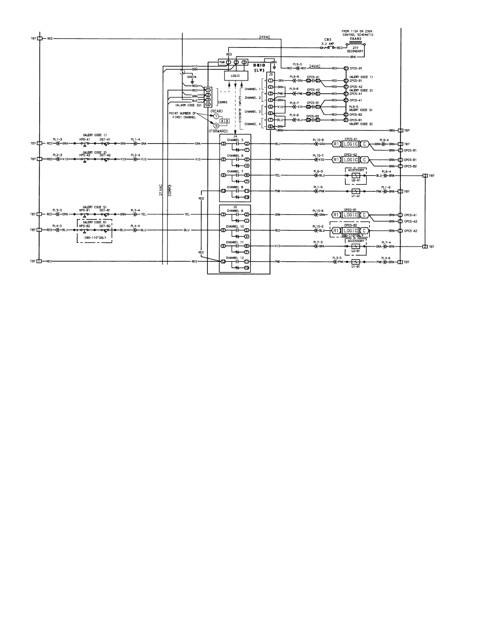
LEGEND
C
— Contactor
CB
— Circuit Breaker
COMM — Communications Bus
CPCS
— Compressor Protection Control Module
DGT
— Discharge Gas Thermostat (Optional)
DSIO
— Relay Module (Low Voltage)
HPS
— High-Pressure Switch
LV
— Low Voltage
PL
— Plug
PWR
— Power
TB
— Terminal Block
TRAN
— Transformer
U
— Unloader
*And associated modular units.
Fig. 11B — 24-V Safety Circuit Wiring (080-110 and Associated Modular Units)
52