Carrier FLOTRONIC II 30GN040-420 User Manual
Page 43
At field configuration step, select 4 to 20 mA loadshed
by entering
(internally powered) or
(externally pow-
ered) when the LSTYP 0 display appears. See Example 7B.
Then enter set points as follows. In this example, set points
are coordinates of the demand limit curve shown in Fig. 9.
Example 7A — Using Demand Limit
(First Log On as Shown in Table 12)
KEYPAD
DISPLAY
COMMENTS
ENTRY
RESPONSE
FLD CFG
Field configuration sub-
function of service function
LSTYP 0
Loadshed is not enabled
LSTYP 1
Loadshed is now enabled
for 2-stage switch control
DEMAND
Demand Limit set points
subfunction of set point
function
DLS1 80
Loadshed 1 currently set
at 80%
DLS1 60
Loadshed reset to 60%
DLS2 50
Loadshed 2 currently set
at 50%
DLS2 40
Loadshed 2 reset to 40%
To Disable Demand Limit:
KEYPAD
DISPLAY
COMMENTS
ENTRY
RESPONSE
FLD CFG
Field configuration sub-
function of service function
ERTYP 0
Scroll past other elements
in the subfunction
LSTYP 1
Loadshed is enabled for
2-stage switch control
LSTYP 0
Loadshed is now disabled
NOTES:
1. Select 2 for internally powered 4 to 20 mA signal load limiting.
2. Select 3 for Carrier Comfort Network loadshed.
3. Select 4 for externally powered 4 to 20 mA signal load limiting.
Example 7B — Using Demand Limit (4-20 mA)
(First Log On As Shown in Table 12)
KEYPAD
DISPLAY
COMMENTS
ENTRY
RESPONSE
FLD CFG
Field configuration subfunction
of service function
ERTYP 0
Scroll past other elements in
the subfunction
LSTYP 0
Loadshed is not enabled
LSTYP 2
Loadshed is now enabled
for 4-20 mA internally-powered
signal control
DEMAND
Demand Limit set points
DL20 100
Maximum demand limit is 100%
DL20 90
Maximum demand limit is 90%
Scrolling past the 4 to 20 mA demand limit set point brings
up the loadshed set points. The loadshed feature is activated
by a redline alert and loadshed commands from the CCN
loadshed option. The first set point is the group number, es-
tablished by the CCN system designer. The second option is
the loadshed demand delta, which defines the percent of the
load to be removed when a loadshed command is in effect.
The third set point is maximum loadshed time, which de-
fines the maximum length of time that a loadshed condition
is allowed to exist. The allowable range for this entry is zero
to 120 minutes.
Subfunction displays date, time, and day of the week.
Reading and Changing Time Display — Time is entered and
displayed in 24-hour time. The day of the week is entered as
a number.
1 = Mon, 2 = Tue, 7 = Sun, etc.
Key is used as the colon when entering time. See
Example 8.
subfunction accesses the leaving chiller fluid alert
limit (LMT) option. The value to be entered here is the num-
ber of degrees above the control set point at which an alert
should be generated. For example, if the control set point is
44 F, and an alert is desired (alert 70) if the fluid temperature
reaches 50 F, then enter 6 for this set point. The allowable
range for this entry is between 2 and 30 (F).
SERVICE FUNCTION — This function allows the techni-
cian to view and input configuration data. Factory configu-
ration data, field configuration data, and service configura-
tion data may be viewed or entered through the keypad and
display module. See Table 9 for a complete listing of con-
figurable items. Whenever a processor module is replaced in
the field, the complete list of configuration codes must be
entered.
Logging On/Logging Off — The service function is pass-
word protected. Therefore, to gain entry to this function,
this password must be entered. Pressing
allows the technician to view, change, or enter configuration
codes. To log off, perform the following keystrokes:
. The service function is once again password
protected.
Software Information —
displays the version
number of the software that resides in the processor
module. The
and
subfunctions are summa-
rized in Table 12.
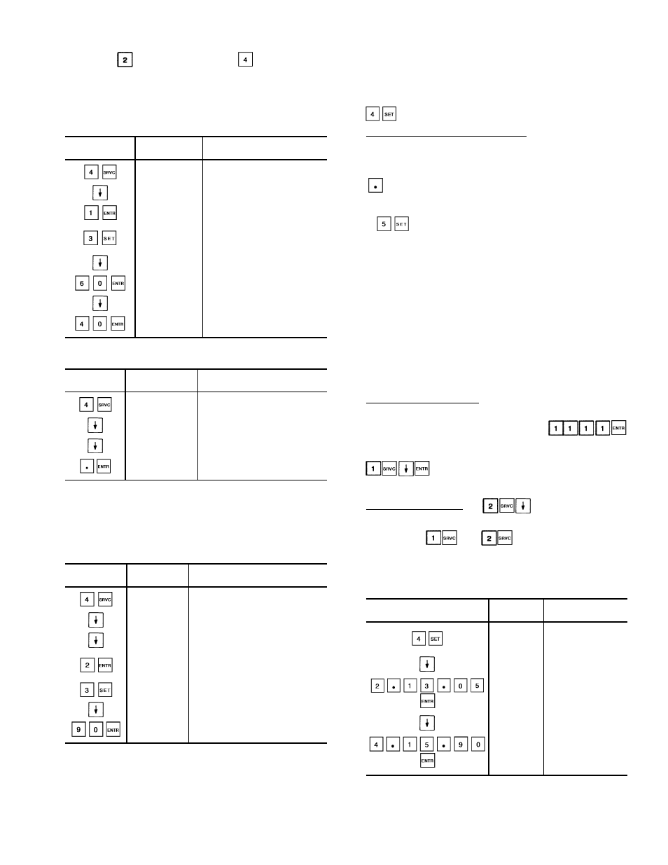
Example 8 — Setting Time of Day and
Day of Week
KEYPAD
DISPLAY
COMMENTS
ENTRY
RESPONSE
TIME
Time display sub-
function of set point
function
MON 16.00
Current setting is
Monday, 4:00 p.m.
TUE 13.05
New setting of
Tuesday, 1:05 p.m.
is entered
and displayed
JAN 01 90
Current date is
Jan. 1, 1990
APR 15 90
New setting
April 15, 1990
is entered
and displayed
43