Carrier FLOTRONIC II 30GN040-420 User Manual
Page 39
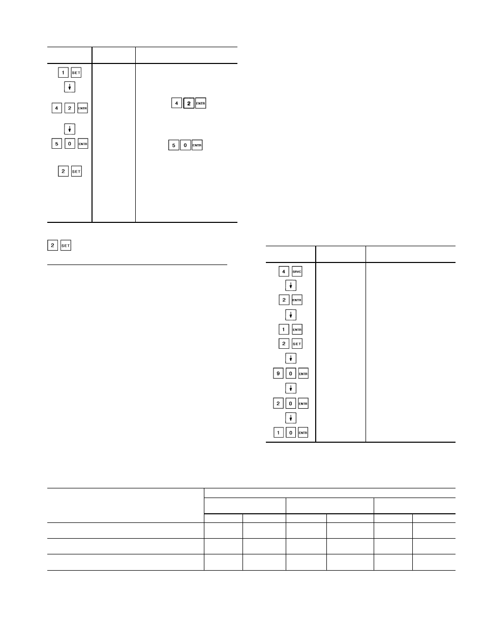
Example 4 — Reading and Changing
Chilled Fluid Set Point
KEYPAD
DISPLAY
COMMENTS
ENTRY
RESPONSE
SET POINT
System set points
CSP1 44.0
Present occupied chilled fluid
set point is 44.0 F
CSP1 42.0
Press the
.
Display shows new occupied
chilled fluid set point is 42.0 F
CSP2 44.0
Present unoccupied chilled fluid
set point is 44.0 F
CSP2 50.0
Press the
. Display
shows new unoccupied chilled
fluid set point is 50.0 F
RESET
Displays the maximum reset
set point. The minimum and
maximum reference reset
set points can also be displayed.
These set points are not
accessible when reset type has
been configured for NONE in
the service function.
Subfunction displays temperature reset set points.
Temperature Reset Based on Return Fluid Temperature —
The control system is capable of providing leaving fluid tem-
perature reset based on return fluid temperature. Because the
temperature difference between leaving and return tempera-
ture is a measure of the building load, return fluid tempera-
ture reset is essentially an average building load reset method.
Under normal operation, the chiller maintains a constant
leaving fluid temperature approximately equal to chilled fluid
set point. As building load drops from 100% down to 0%,
entering cooler fluid temperature drops in proportion to load.
Thus, temperature drop across the cooler drops from a typi-
cal 10 F (5.5 C) at full load to a theoretical 0° F (0° C) at no
load. See Fig. 5.
At partial load, leaving chilled fluid temperature may be
lower than required. If this is allowed to increase (reset), the
efficiency of the chiller increases. Amount of reset can be
defined as a function of cooler temperature drop, as shown
in Fig. 5. This is a simple linear function that requires
3 pieces of input data for the set function that will vary de-
pending on measurement method used as follows (see
Table 11):
NOTE: Reset set points are not accessible unless the reset
function is enabled first. This is done as a field
configuration. Select one of the 4 choices for type of reset:
Return Fluid Reset, External Temperature Reset, 4-20 mA
External Signal Reset, or 4-20 mA Internal Signal Reset.
If dual set point control is enabled (see Field Wiring sec-
tion on page 69), the amount of reset is applied to whichever
set point is in effect at the time.
Examples 5A-5C demonstrate how to activate reset. Ex-
ample 6 demonstrates how to change the type of reset. As-
sume that reset is to be based on return fluid temperature,
the desired reset range is to be 0° to 10° F (0° to 5.5° C) and
full load is a 10° F (5.5° C) drop across the cooler. See
Fig. 5.
Activating reset based on external temperature or
4-20 mA signal is done the same way, except the reference
set point range is –40° to 240° F (–40° to 115° C), or 4 to
20 mA depending on which method was selected at the field
configuration step.
Example 5A — External Reset
In this example, the unit set point is reset from full load
at 90 F (32 C) to a maximum reset value of 10 F (5.5 C) at
20 F (–6.7 C) outdoor ambient.
NOTE: All temperatures given in this example are in F.
KEYPAD
DISPLAY
COMMENTS
ENTRY
RESPONSE
FLD CFG
CRTYP 0
Scroll past to reset type
CRTYP 2
External reset selected
ERTYP 0
Scroll past to space
thermistor sensor selected
ERTYP 1
OAT selected
RESET
CRT2N 0
Temperature for no
reset is 0
CRT2N 90
Temperature for no
reset is 90
CRT2F 0
Temperature for maximum
reset is 0
CRT2F 20
Temperature for maximum
reset is 20
CRT2D 0
Maximum reset is 0
CRT2D 10
Maximum reset is 10
Table 11 — Reset Amounts
INPUT DATA DESCRIPTION
MEASUREMENT METHOD
4-20 mA
OAT/Occupied Space
or Internal/External
Return Water
Variable
Limits (F)
Variable
Limits (F)
Variable
Limits (F)
Maximum Reset Amount — Allowable range for
maximum amount which LWT is to be reset.
CRT1
–30 to 30
CRT2D
–30 to 30
CRT3D
–30 to 30
Maximum Reset Reference — Temperature at
which maximum reset occurs.
—
—
CRT2F
–40 to 240
CRT3F
0 to 15
Minimum Reset Reference — Temperature at
which no reset occurs.
—
—
CRT2N
–40 to 240
CRT3N
0 to 15
LEGEND
OAT — Outdoor-Air Temperature
LWT — Leaving Fluid Temperature
39