Carrier FLOTRONIC II 30GN040-420 User Manual
Page 29
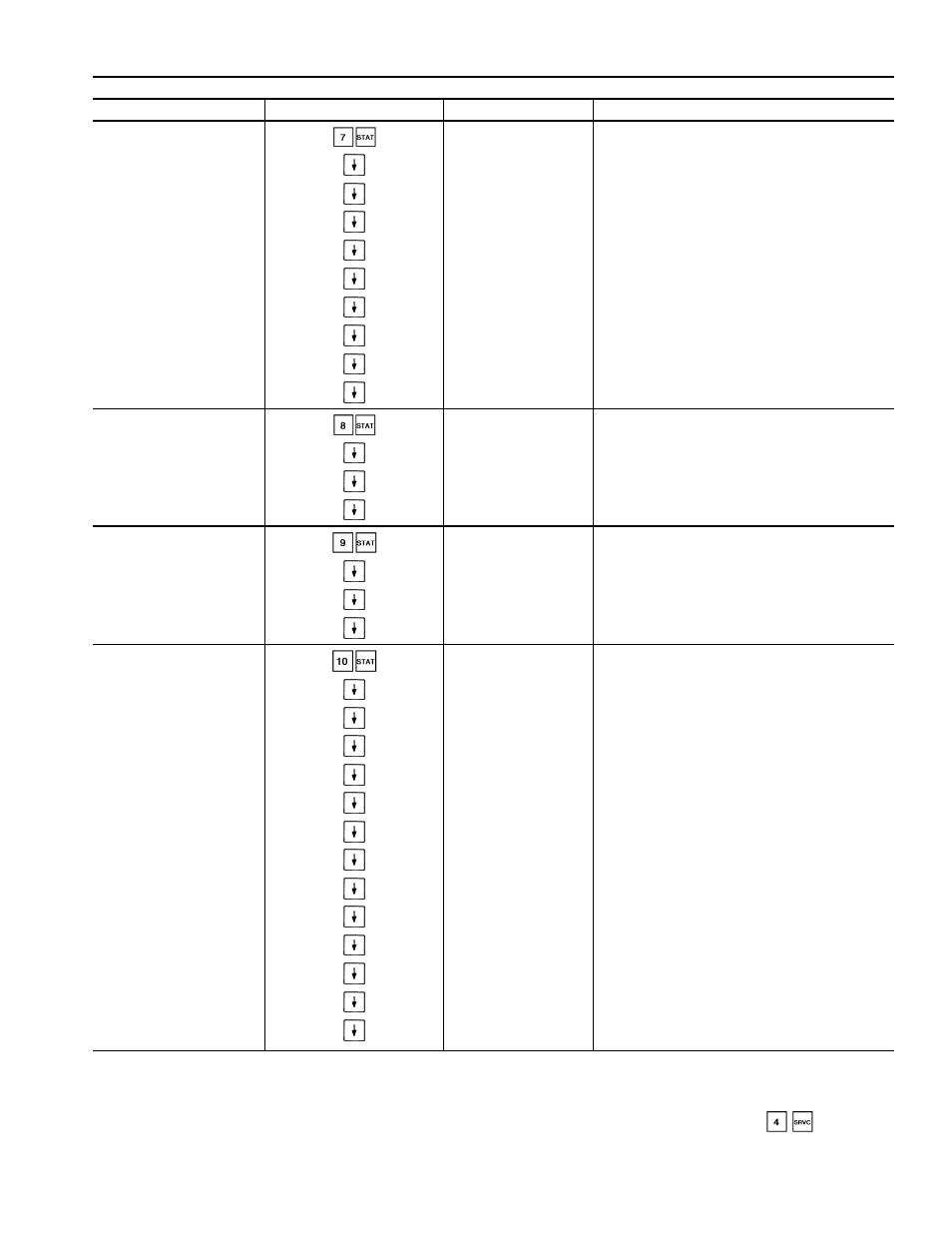
Table 9 — Keypad Directory (cont)
STATUS (cont)
SUBFUNCTION
KEYPAD ENTRY
DISPLAY
COMMENT
7 PRESSURE
PRESSURE
Refrigerant System Pressure (psig)
MM DD YY
Date of Last Calibration
DPA X
Circuit A Discharge Pressure (psig)
SPA X
Circuit A Suction Pressure (psig)
XXXX XXX
Circuit A Discharge/Suction (psig)
OPA X
Circuit A Oil Pressure Differential (psig)
DPB X
Circuit B Discharge Pressure (psig)
SPB X
Circuit B Suction Pressure (psig)
XXXX XXX
Circuit B Discharge/Suction (psig)
OPB X
Circuit B Oil Pressure Differential (psig)
8 ANALOG
ANALOG
Status of Analog Inputs
REF X
Transducer Supply Voltage (volts)
LMT X†
Demand 4-20 mA Signal (mA)
RST X†
Reset 4-20 mA Signal (mA)
9 INPUTS
SW INPUT
Status of Switch Inputs
SPW X†
Dual Set Point Switch (open/closed)
DL1 X†
Demand Limit Switch 1 (open/closed)
DL2 X†
Demand Limit Switch 2 (open/closed)
10 OUTPUTS
OUTPUTS
Status of Outputs
ALMR X
Alarm Relay K3 (on/off)
FRA1 X
Fan Relay K1 (on/off)
FRA2 X
Fan Relay K2 (on/off)
FRB1 X
Fan Relay K4 (on/off)
FRB2 X
Fan Relay K5 (on/off)
CHWP X†
Cooler Water Pump Relay K6 (on/off)
ULA1 X
Unloader A1 (on/off)**
ULA2 X†
Unloader A2 (on/off)**
ULB1 X
Unloader B1 (on/off)**
ULB2 X†
Unloader B2 (on/off)**
LLSA X
Liquid Line Solenoid A
LLSB X
Liquid Line Solenoid B
EXVA X
EXVA Percent Open†
LEGEND
CCN — Carrier Comfort Network
EXV
— Electronic Expansion Valve
MOP — Maximum Operating Pressure
*Will read ALARM or ALERT as appropriate.
†Must be configured.
**If applicable.
††Not manually resettable.
NOTE: If metric option is selected under
, temperature
expressed as Celsius and pressure will be expressed as kPa.
29