Tweco 400 MSTP Arcmaster User Manual
Page 37
31
4.0 SEQUENCE OF OPERATION
NOTE: Parameter Buttons are used to select the parameters to be set. The LED’s
show which function is being adjusted on the weld sequence graph. Refer to
Symbols Table located in the front of the manual for Symbol descriptions.
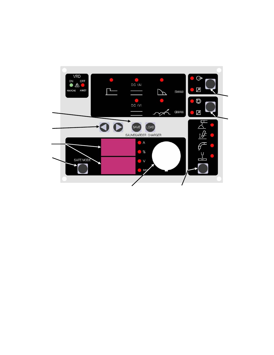
Figure 6. 400 MSTP Front Panel
1. Contactor Function: Pressing this buttons enables Contactor functions.
2. Remote Functions: Pressing this buttons enables remote current functions.
3. Digital LED Displays: Welding amperage, Voltage and parameter values are displayed in this window.
Internal warnings such as over temperature, low or high input voltage applied are signaled to the operator
by a warning sound and error message on the screen.
4. Save/Load Buttons: By using the Save & Load buttons the operator can easily save up to 5 welding
parameter programs.
5. Control Knob: Allows the operator to adjust the output amperage/voltage within the entire range of the
power source, also used to set each parameter value.
6. Process Button: This button selects between STICK, Lift TIG, and MIG modes.
7. Scroll Buttons: This button select between HOT START, WELD CURRENT, and ARC
CONTROL while in STICK and Lift TIG modes and selects between WELD VOLTAGE and
INDUCTANCE CONTROL while in MIG mode. This button is also used in conjunction with
the Save/Load buttons to save and load welding programs.
8. SAFE MODE: SAFE (Special Application Function Environment) is a mode of operation that
the 400MSTP of welding power source can enter in order to customize the welder for a special
application. See section 4.06.
7
4
3
5
6
2
1
8