02 functional block diagram, 03 transporting methods, Figure 2. 400 mstp model functional block diagram – Tweco 400 MSTP Arcmaster User Manual
Page 18
12
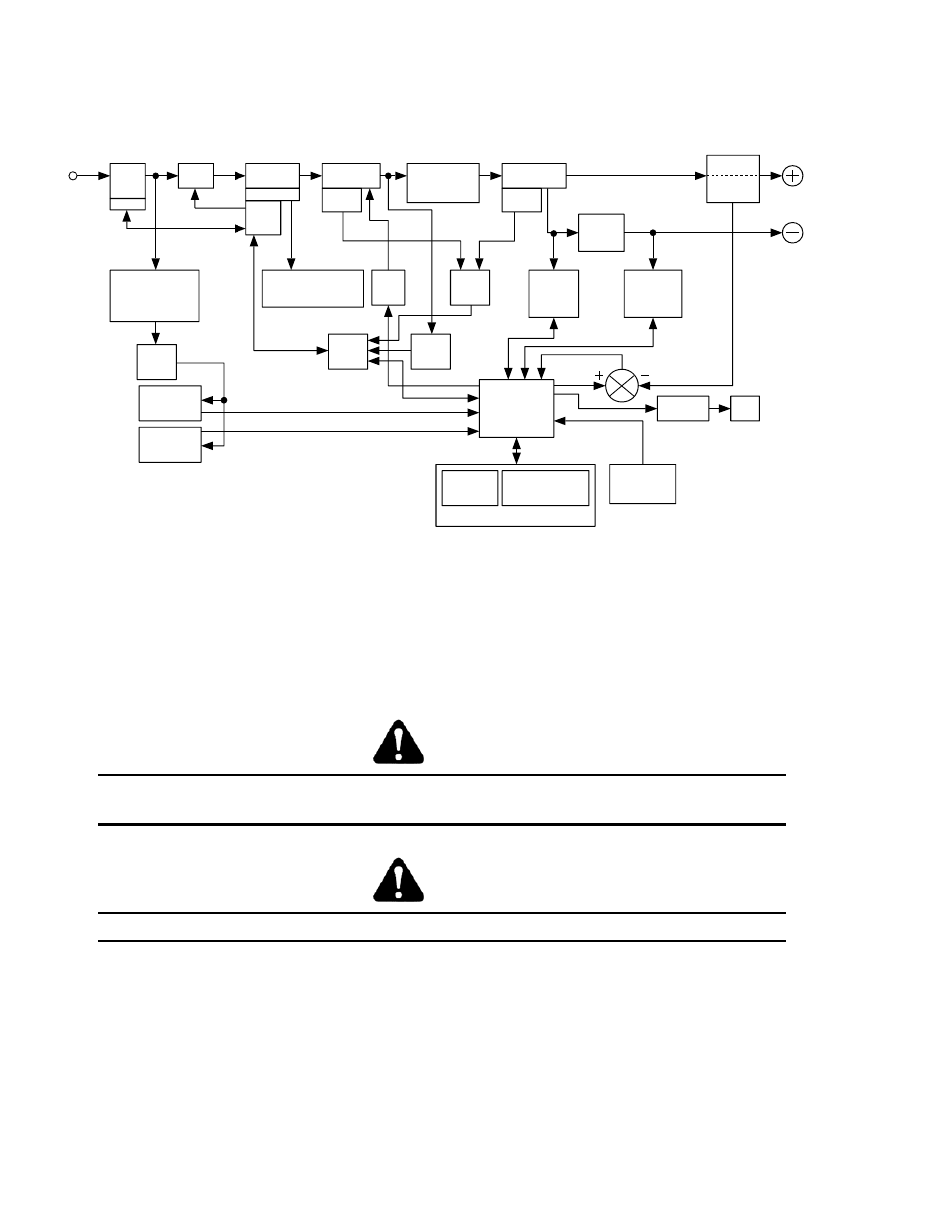
2.02 Functional Block Diagram
Figure 2 illustrates the Functional Block Diagram of the 400 MSTP-power supply.
To each control circuit
Main
Circuit
Switch
Filter
Input
Diode
Capacitor
DC Power
Primary
Voltage
Sensor
IGBT
Inverter
Themal
Detector
Main
Transformers
(T1)
Output
Inductor
Output
Diodes
Transformer
(HCT1)
Hall Current
Lift T ig Mode
Output Short
Sensing
Circuit
Stick Mode
VRD
Sensing
Circuit
Thermal
Sensor
Circuit
Drive
Circuit
+/-15VDC +18VDC
+24VDC +5VDC
Trouble
Sensing
Circuit
14PIN
Receptacle
(CON1)
Current
Adjustment
Circuit
Reference
Adjustment &
Mode select Switch
Panel Circuit Boad
Sequence
Control
Fan Control
Circuit
Fan
Input
Power
Primary
Circuit
Sensor
Down
Transformers
AC115V,AC24V
(T3)
Over
Current
Protect
19PIN
Receptacle
(CON2)
Themal
Detector
14PIN-19PIN
Select Switch
(S3)
Figure 2. 400 MSTP Model Functional Block Diagram
2.03 Transporting Methods
This unit is equipped with a handle for carrying purposes.
WARNING 1
ELECTRIC SHOCK can kill. DO NOT TOUCH live electrical parts. Disconnect input power conductors
from de-energized supply line before moving the welding power source.
WARNING 2
FALLING EQUIPMENT can cause serious personal injury and equipment damage.
Lift unit with handle on top of case.
Use handcart or similar device of adequate capacity.
If using a fork lift vehicle, place and secure unit on a proper skid before transporting.