02 remote pendant arctime, 02 remote pendant arctime -2, N7500 maintenance – Tweco N7500 User Manual
Page 48
MAINTENANCE 7-2
Manual 89250890
N7500
MAINTENANCE
The following checklist can be used as a guide for routine maintenance.
• Check warning labels for readability.
• Check sheet metal panels, plates, and covers on the Control Box, Remote Pendant, and Torch Head. All screws,
fasteners, and connectors should be firmly secured. Heavily corroded or damaged panels, damaged fasteners
or connectors should be replaced.
• Check all wiring and hoses to the Control Box, Remote Pendant, and Torch Head. Repair or replace any wires,
cables, or hoses that have cracked or damaged insulation or frayed connections.
• Check Control Box internal connections including circuit board connectors. Any loose or corroded connections
should be repaired.
• Check any connections to travelers, fixtures, etc.
• Check all Control Box switches and controls. Damaged or broken switches or controls should be replaced.
• Check Remote Pendant control panel surface, bumper, connector, and controls. Cracked, torn, or peeling Remote
Pendant control panel surface should be replaced. If any of the control buttons or rotary dial are inoperable the
Remote Pendant should be replaced. If the rotary dial knob is broken, missing, or malfunctioning the rotary
dial knob should be replaced.
• Check Torch Head nozzle, air plenum housing, shield, motor, busbar connection, and motor cable. Heavily
corroded or damaged nozzle, air plenum housing, or shield should be replaced.
• Check and log N7500 Arctime hours using the Remote Pendant.
7.02 Remote Pendant ARCTIME
Arctime will show the N7500 arctime when the unit is turned ON. This display will update as the N7500 is used.
1. Position the power switch located on the side of the Control Box labeled “POWER OFF” & “POWER ON” to the
“ON” position. Notice the electrode will retract for several seconds and stop.
2. The Mode Indicator Display on the Remote Pendant will light up on the “Menu Setting” (Default display whenever
the unit is powered up).
3. Using the down “Mode Selector”
button move the cursor to highlight “Arctime” and press the “OK”
OK
button.
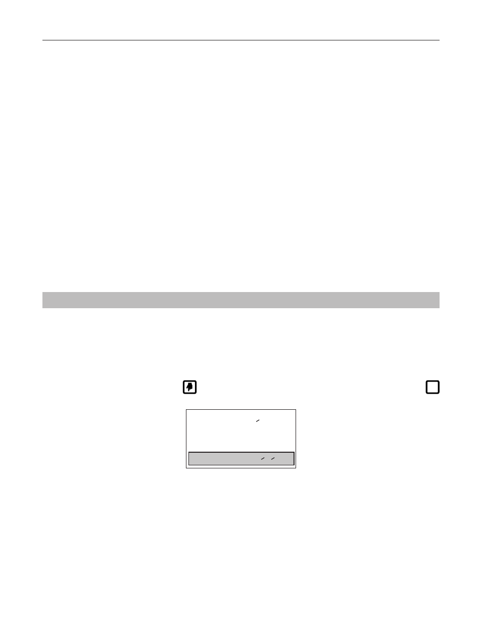
ART# A-10840_AB
0.0HR
Arctime
0.2 Sec
NoCurrent Detect
Normal
Figure 7-2: Arctime Screen
4. Log the Arctime hours and the date the reading was taken onto a log sheet for your maintenance record.