06 remote pendant installation, 06 remote pendant installation -8, N7500 assembly and installation – Tweco N7500 User Manual
Page 34: Ok tr v jo g stop, Roug h star t, 5 am p 5 am p, Control box (viewed from cabinet right side)
N7500
ASSEMBLY AND INSTALLATION
ASSEMBLY AND INSTALLATION
4-8
Manual 89250890
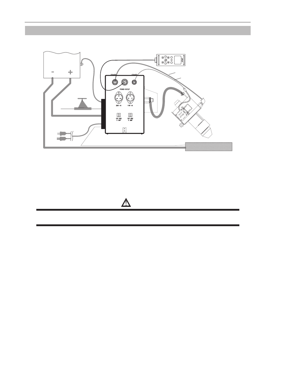
4.06 Remote Pendant Installation
(Rear panel assembly
not shown for clarity)
N7500 Gouging Syste
m
Automatic Contro
l
anel assembly
n for clarity
REMOTE PENDANT
REMOTE PENDANT CABLE
OK
TR
V
JO
G
STOP
T
UNE
ROUG
H
STAR
T
MOTOR CABLE -
CONTROL BOX TO
TORCH HEAD
AIR HOSE
DC POWER
CABLE (+) OUT
TORCH HEAD
GROUND CABLE (–)
DC POWER CABLE (+) IN
INCOMING
AIR LINE
POWER
SUPPLY
TORCH HEAD
PENDANT
AIR OUT
MOUNTING
FIXTURE
AIR INLET
ART# A-10854_AB
POWER SUPPLY
COMMUNICATION CABLE
AIR REGULATOR
OU
5 AM
P
5 AM
P
WORK PIECE
SIGNAL
WIRE
GROUND CABLE (–)
CONTROL BOX INPUT
AC POWER CABLE
CONTROL BOX
(VIEWED FROM CABINET RIGHT SIDE)
120V
OR
220V
THESE CONNECTIONS
ON OTHER SIDE
S
Figure 4-12: Assembly Stage 3
14. Connect the Remote Pendant Cable Assembly to the Remote Pendant and the Control Box. Cable has a
large 7 pin connector at each end. Refer to "Table 4-7: Cable Identification" on page 4-3.
15. Plug the travel system grounded power cord into the receptacle labeled “POWER OUTLET”.
WARNING
Select the receptacle voltage that correctly matches the plug and power requirements of the Carriage
System.