Assembly and installation n7500 – Tweco N7500 User Manual
Page 31
ASSEMBLY AND INSTALLATION
N7500
Manual 89250890
4-5
ASSEMBLY AND INSTALLATION
WARNING
Confirm the DC Power Supply is OFF before beginning the next step.
5. Connect the positive (+) Power Supply cable(s) of the DC Power Supply to the busbar terminal on the back
side of the Control Box labeled “POWER SUPPLY IN”. This connection must be wrench tight to avoid over
heating of the connection. Refer to "Table 3-13: Power Cable Requirements" on page 3-10 in this manual
for proper amount and size Power Supply cabling that you plan to use.
NOTE
It is recommended to use a minimum of two Power Cable assemblies with the N7500. The cables should
be connected at the same points on the Control Box. Refer to "Table 3-13: Power Cable Requirements"
on page 3-10.
6. Connect the negative (-) cable(s) of the DC Power Supply to the work piece.
7. A signal wire (not supplied) must be attached to the work piece and the other end to the ground post on
the left side of the Control Box labeled “SIGNAL WIRE”.
NOTE
Use standard #12 insulated copper wire as your signal wire. It must be long enough to prevent stress
on the Control Box connection.
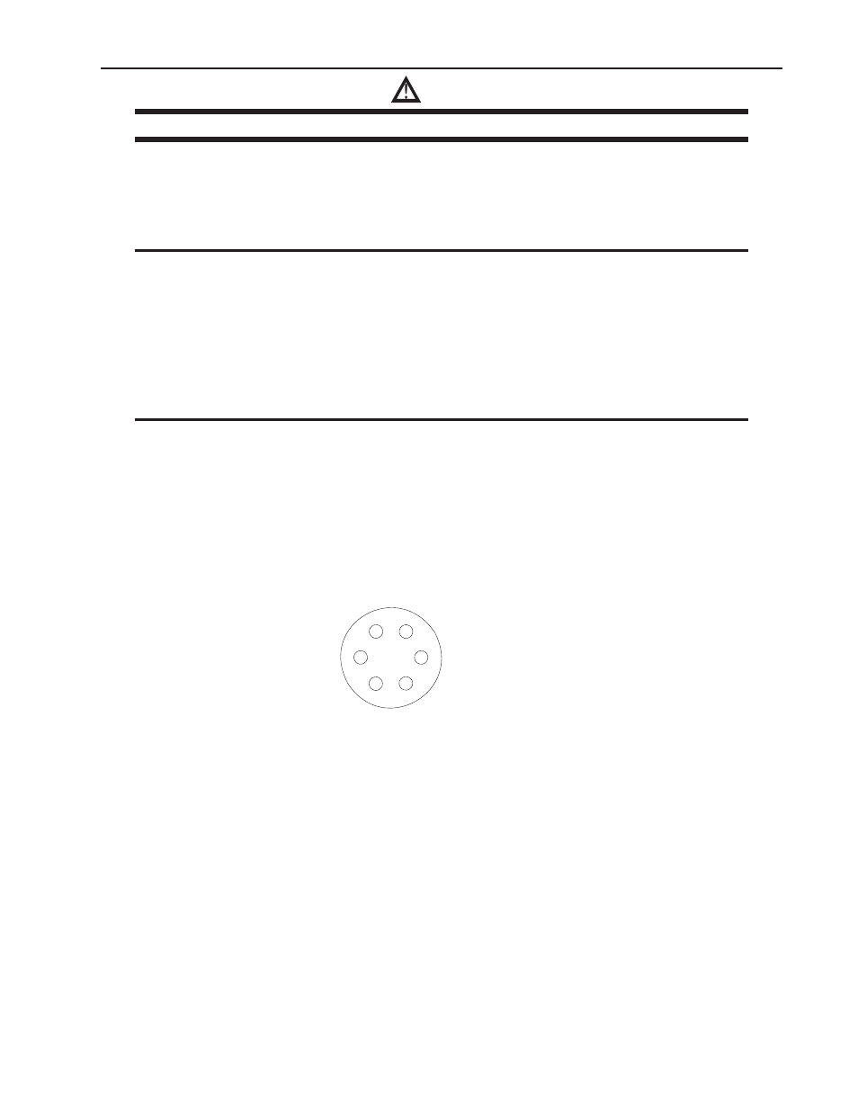
8. Connect the Power Supply Communication Cable Assembly (6 pin female connector) to the side of the
Control Box labeled “POWER SUPPLY” and run it back to the Power Supply. Refer to "Table 4-7: Cable
Identification" on page 4-3 for cable identification. "Figure 4-9: Power Supply Comm. Cable Pin Configu-
ration" below illustrates the pin arrangement for the Power Supply Communication Cable and "Table 4-10:
Standard Wiring Connections" has the wire connection schedule for several common power supplies. If
your Power Supply is not listed here please refer to the Owner’s manual of your Power Supply for correct
wiring instructions.
CONTROL BOX POWER SUPPLY
COMMUNICATION CABLE PIN LAYOUT
B
A
C
D
E
F
PIN F BLACK #2
PIN A BLACK #1
ART# A-10832_AD
Figure 4-9: Power Supply Comm. Cable Pin Configuration