05 torch head installation, 05 torch head installation -7, Assembly and installation n7500 – Tweco N7500 User Manual
Page 33
ASSEMBLY AND INSTALLATION
N7500
Manual 89250890
4-7
ASSEMBLY AND INSTALLATION
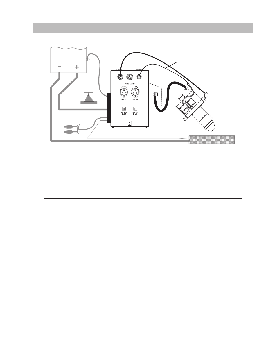
4.05 Torch Head Installation
Make connections from Control Box to the Torch Head. See "Figure 4-11: Assembly Stage 2".
(Rear panel assembly
not shown for clarity)
MOTOR CABLE -
CONTROL BOX TO
TORCH HEAD
AIR HOSE
DC POWER
CABLE (+) OUT
TORCH HEAD
GROUND CABLE (–)
DC POWER CABLE (+) IN
INCOMING
AIR LINE
POWER
SUPPLY
TORCH HEAD
PENDANT
AIR OUT
MOUNTING
FIXTURE
AIR INLET
ART# A-10848_AC
POWER SUPPLY
COMMUNICATION CABLE
AIR REGULATOR
5 AM
P
5 AM
P
WORK PIECE
SIGNAL
WIRE
GROUND CABLE (–)
CONTROL BOX INPUT
AC POWER CABLE
CONTROL BOX
(VIEWED FROM CABINET RIGHT SIDE)
120V
OR
220V
N7500
THESE CONNECTIONS
ON OTHER SIDE
S
Figure 4-11: Assembly Stage 2
9. Mount the Torch Head to the vertical adjustment assembly located on the travel system or fixed stationary
fixture using the mounting hardware supplied with the Torch Head. Further adjustments will be discussed
in the operating section of this manual. See "5.02 Position Torch Head" and "5.03 Insert the Electrode"
on page 5-2.
NOTE
Tuning the mounting position of the Torch Head or adjusting the traveler fixture or carriage system may
be required to achieve best gouging results.
10. Connect the DC power cable(s) to the Torch Head busbar and to the busbar terminal on the back side of the
Control Box labeled “POWER SUPPLY OUT”. These connections must be wrench tight to avoid overheating
the connection. Slide the cable boot over the busbar on the Torch Head. Use the 1/2”-13 hex head bolt
and nut supplied for the cable connection on the Torch Head busbar.
11. Return the Control Box Power Supply cover plate to its original position and tighten both screws.
12. Connect the Air Hose Assembly to the Torch Head and to the side of the Control Box labeled “AIR OUT”.
Slide the rubber boot over the connection on the Torch Head.
13. Connect the Torch Head Motor Cable Assembly to the connector on the side of the Control Box labeled
“TORCH HEAD” and the other end to the motor cable connection on the Torch Head. This cable has a 6
pin connector at each end. Refer to "Table 4-7: Cable Identification" on page 4-3.