04 control box installation, 04 control box installation -4, N7500 assembly and installation – Tweco N7500 User Manual
Page 30
N7500
ASSEMBLY AND INSTALLATION
ASSEMBLY AND INSTALLATION
4-4
Manual 89250890
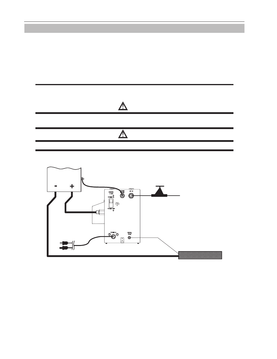
4.04 Control Box Installation
Determine where the Control Box should be located in relationship to where the gouging will take place. It is not
recommended to carry the Control Box on any travel system other than the Victor Arcair Titan
®
Machine Carriage
due to the added weight of the Control Box and the weight of the power cables coming from the DC Power Supply.
The Control Box can be secured to a stationary surface with the mounting brackets on both sides. Refer to "Table
3-2: Control Box Features" on page 3-2 for the mounting brackets and "Figure 3-4: RIGHT Side of Control Box"
and "Figure 3-5: BACK of Control Box" on page 3-3 for bracket locations.
NOTE
DO NOT force connections. All connectors should be fastened easily. Be sure to tighten connections
as you go through each step. Avoid crimping hoses or wires.
WARNING
Select the receptacle voltage that correctly matches the plug and power requirements of the Carriage
System.
WARNING
Confirm that the Power Supply and Control Box Power In switches are OFF.
WORK PIECE
SIGNAL WIRE
GROUND CABLE (–)
CONTROL BOX INPUT
AC POWER CABLE
DC POWER CABLE (+) IN
INCOMING
AIR LINE
POWER
SUPPLY
CONTROL BOX
(VIEWED FROM CABINET LEFT SIDE)
ART# A-10850_AC
POWER SUPPLY
COMMUNICATION CABLE
AIR REGULATOR
GROUND CABLE (–
)
120V
OR
220V
MAX 100 psi
(Rear panel assembly
not shown for clarity)
Figure 4-8: Assembly Stage 1
1. Connect the air regulator to the side of the Control Box labeled “AIR IN”. Preset the regulator to the rec-
ommended operating pressure based on "Table 3-14: Compressed Air Input Requirements" on page 3-10.
(The compressed air inlet and outlet fittings on the Control Box are 1/2-14 NPT.)
2. Connect the incoming shop compressed air line to the air regulator. Charge the shop compressed air sup-
ply to the air regulator on the Control Box’s AIR IN side to confirm air pressure is within recommended
specifications. Refer to the specifications listed on the Control Box nameplate.
3. Attach the AC Power Cable to the connector labeled “POWER IN”.
4. Loosen the screws holding the Control Box rear cover plate. Re-position and tighten one screw.